Owner’s Manual
Graphic
____________________________________________________________________________________
Issue Date: November 2025
Revision Date: August 2026
NOTE: Carefully read, understand and follow the instructions provided in this manual, and keep it in a safe place for future reference. If you have any doubt whatsoever regarding the use or care of your vehicle, please visit a Authorized Mahindra Service Center for assistance or advice.
MAHINDRA & MAHINDRA LTD. GATEWAY BUILDING, APOLLO BUNDER, MUMBAI - 400 039
www.mahindra.com


FOREWORD
Thank you for choosing the Mahindra vehicle.
We are privileged to welcome you to the Mahindra family.
Your vehicle represents Robust Quality, Ruggedness, Safety, Precision Workmanship and Distinctive Styling, which are our traditional values.
This documents contains important information on vehicle operation, that will help you make full use of the technical features available. To exercise better control on road, we suggest you to please take time to read, understand and familiarise with vehicle and its features. Following the instructions and recommendations in this manual will help assure safe and enjoyable operation of your vehicle.
When it comes to service, note that your Authorized Mahindra Service Center knows your vehicle best, has company trained Technical Experts, Mahindra Genuine Parts and very much cares about your satisfaction.
We extend our best wishes for safe and pleasurable motoring.
Graphic

MAHINDRA & MAHINDRA LTD.
1. The Brand official website : https://auto.mahindra.com/
2. Owner’s Manual Website: https://mvault.mahindra.com/owners_manual
3. Mobile App : Interactive Vehicle manual in the M4U (Mahindra for You).


  Important Information – Quick Reference
   
 
We strongly urge that you read the information provided in pages referred hereunder which will help in road safety and prevent inconvenience.
1
Warranty Coverage.............................................................................................
Refer WSIG* (P.g. 16)
2
Roadside Assistance....................................................................................
Refer WSIG* (P.g. 12)
3
Schedule Service (Free/Paid).................................................................
Refer WSIG* (P.g. 26)
4
Maintenance Schedule Chart.................................................................................
Refer WSIG* (P.g. 28)
5
Lubricants and Capacities.............................................................................
Refer WSIG* (P.g. 30)
6
Location of Vehicle Identification Number (VIN).................................................
Refer (P.g. 1-11)
7
Location of Fuse Box and Fuse Details............................................................
Refer (P.g. 10-5)
8
Changing a Flat Tyre................................................................
Refer (P.g. 10-15)
9
Understanding the Warning Lamps..........................................................
Refer (P.g. 3-25)
10
Use of Seat Belts and Child Restraint......................................
Refer (P.g. 2-9)
11
Understanding the Airbag Function.........................................................
Refer (P.g. 2-24)
12
If your Vehicle is Submerged.....................................................
Refer (P.g. 7-14)
13
Driving through Water..................................................................................
Refer (P.g. 7-15)
14
Opening and Closing the Bonnet.........................................
Refer (P.g. 4-24)
15
Location of Battery and its Maintenance.....................................
Refer (P.g. 11-13)
16
Charging System.....................................
Refer (P.g. 9-1)
*Warranty and Service Information Guide
Note: In view of our policy of continuously improving our products, we reserve the right to alter specifications, designs or features without prior notice and without liability. We recommend you to refer the Variant Matrix in the Brand official website or contact the nearest Authorized Mahindra Service Center for the list of features applicable to your vehicle.
The vehicle’s software and security measures are subject to ongoing development. Similar to computers and mobile device operating systems, the software and security features of the vehicle might also receive irregular updates.
1 GENERAL AND SAFETY PRECAUTION
1.1 Servicing and Summary Data
We suggest that you record the vehicle servicing data in the Warranty and Service Information Guide for future references.
We recommend you always use Mahindra Genuine Parts, when performing repairs on the vehicle.
For all issues concerning the vehicle and for any need of Genuine spare parts, contact a Authorized Mahindra Service Center.
1.2 Electric Vehicle System
High-Voltage Components
Graphic
A
Integrated Power Distribution Unit (IPDU)
E
HV Battery Pack
B
Cabin Heater
F
Battery Heater
C
Traction Motor and MCU
G
AC Compressor
D
High-Voltage Cables
   
XUV3XO EV operates differently compared to an internal combustion engine vehicles as it is powered by a 350 V (approx) HV battery power pack. Vehicle battery must be charged with electricity before driving it. Once the ignition is turned ON, stored energy in battery pack gradually decreases and if discharged completely to 0% then will not drive until battery pack is recharged. Charging time varies depending on HV battery SOC and ambient conditions. For more information refer charging section.
XUV3XO EV is equipped with vacuum assisted hydraulic brakes, also assisted by regenerative braking.
XUV3XO EV is an eco-friendly vehicle that does not release any toxic emissions like carbon monoxide, carbon dioxide and nitrogen oxide.
As there is no noise from electric motor, you will hear noises like tyre, wind etc. also during charging you may hear fan, compressor, contactor and relay noises.
Pay special attention to the pedestrians since there is no engine noise. The pedestrian may not know the vehicle is approaching or moving or about to move, and can step into the path of vehicle travel.
For preventing damage to the HV battery pack:
•  Never allow the HV battery to fully discharge.
•  Discharging the HV battery to 0% may cause damage to the vehicle components.
•  Do not use the Battery as a stationary power source. This will void the warranty.
•  Do not expose the vehicle to very high temperatures for longer duration.
•  Do not use High-Voltage (HV) battery for any other purpose, consult a Authorized Mahindra Service Center or manufacturer for help.
If you let the battery discharge to 0%, other components may be damaged or need to be replaced (Ex: Low voltage battery).
In these cases, you are liable for repair and/or transportation costs.
The warranty does not cover discharge-related expenses.
XUV3XO EV uses high voltage and current. Failure to follow the proper handling instructions may cause serious injury or death.
XUV3XO EV cannot be push started or tow-started. Attempting to do so may cause traction motor damage.
XUV3XO EV uses high voltage systems, these systems maybe hot during charging and driving, also some times in shut off condition. Be careful of both the high voltage and the high temperature. Obey the labels that are attached to the vehicle.
Never disassemble, remove or replace high-voltage parts and cables as well as their connectors. High voltage cables are colored orange.
Connecting unauthorized electrical accessories is not recommended.
Disassembling, removing or replacing HV components or cables can cause severe burns or electric shock that may result in serious injury or death. The vehicle high voltage system has no user serviceable parts. Take your vehicle to the Authorized Mahindra Service Center for any necessary maintenance/repair.
Always check and ensure enough SOC is available in the HV battery before starting the journey. Verify the same with the help of “State of charge (SOC)” and “Range”values displayed in the instrument cluster.
•  Make sure to turn off ignition and take the key out of the vehicle before leaving.
•  Always engage the parking brake before getting out of the vehicle.
•  Strictly do not allow untrained / non designated people to access EV system and appraise first responders that this vehicles is an Electric Vehicle, in case of any kind of unexpected incident/ events.
•  Vehicle will not run with completely discharged battery. At low SOC avoid continuous and aggressive tip in and tip out, this will result in higher energy consumption. Try to maintain a steady speed with moderate acceleration for getting the maximum efficiency.
•  Driving in down gradient, when accelerator pedal is released, regenerative braking will provide some energy to recharge battery pack and simultaneously assists in deceleration.
•  You may hear some sound and feel vibration in drive that are normal:
–  Traction motor makes lighter sound during its operation, also will be higher in deceleration of the vehicle.
–  Brake vacuum pump makes sound whenever it is in operation and ignition ON.
–  HV contactor makes tak noise when vehicle is switched ON/OFF.
–  AC compressor makes sound while in operation.
•  If the ambient temperature is between –10 °C to 0 °C, there will be considerable increase in charging time, also performance drop during drive.
•  If the ambient temperature is less than –10 °C, plug in the charger and wait for minimum 30 minutes for the charging to initiate (verify using HV battery charging lamp ON in cluster).
•  Performance of battery will decrease with time and usage. This does not indicate any defect in battery pack.
•  Once the battery pack has reached its end of life, its charge holding capacity reaches below specific level, it may require an inspection from Authorized Mahindra Service Center and may require battery pack replacement.
•  It is recommended and mandatory that during process of the battery or vehicle / components disposal, owner should contact Authorized Mahindra Service Center for guidance and information on recycling or proper disposal without causing any environmental pollution.
If the vehicle cannot be assessed for extent of damage, do not touch the vehicle and contact nearest Authorized service center or customer care executive for support.
Don’t carry out any welding work on vehicle outside Authorized Mahindra Service Center.
1.3 Additional Safety Precautions
1. XUV3XO EV does not move unless charge cable is unplugged from charge port.
2. It is recommended to apply park brake after switching off the ignition and before leaving the vehicle.
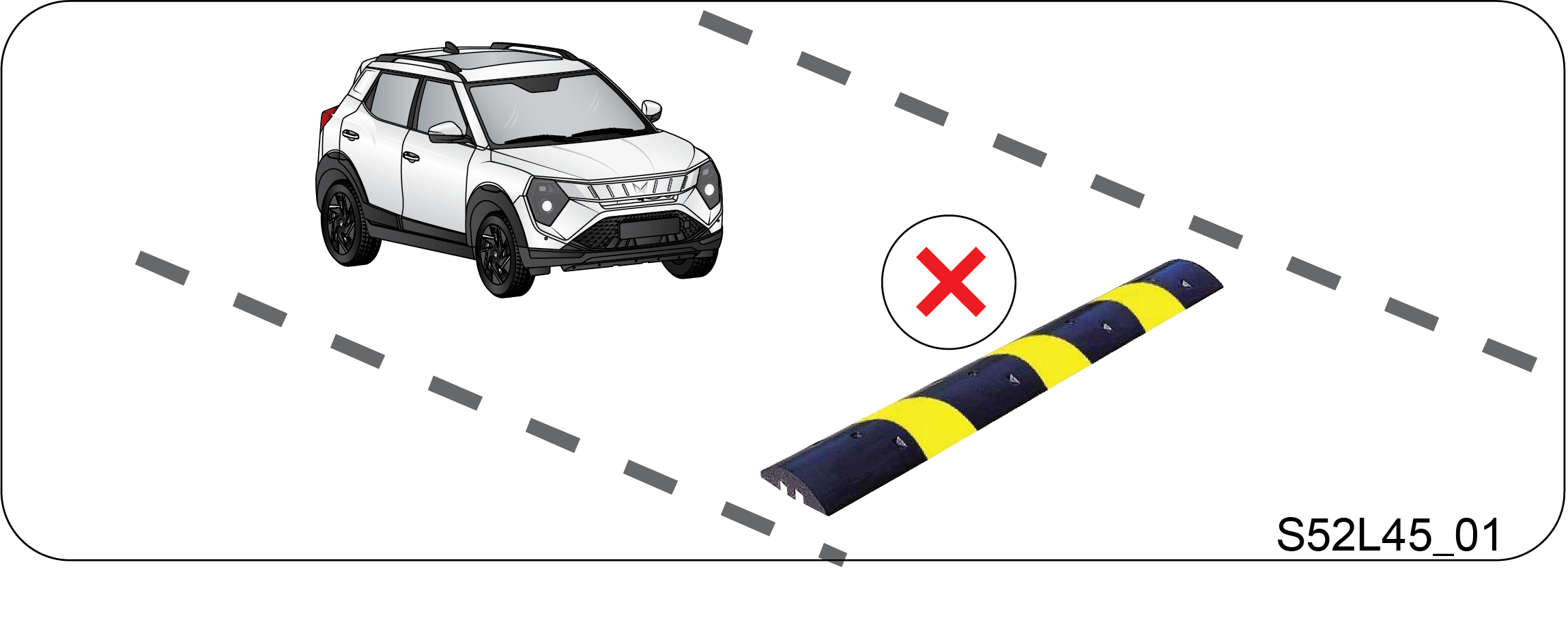
3. Vehicle should be driven < 20 km/h speed on speed breakers and rough roads to avoid damage to the battery pack under the vehicle.
4. Tyres used in the vehicle are tubeless, designed for all weather conditions. They provide best driving range with improved road grip.
In case of vehicle shutdown, contact a Authorized Mahindra Service Center.
1.4 End Of Life - Disposal
As this is an electric vehicle, many electric and electronic parts are used in its system. It should be disposed without causing pollution to environment.
Your XUV3XO EV contains a sealed Li-ion high voltage battery. If the Li-ion battery is disposed improperly, there is a risk of severe burns and electrical shock that may result in serious injury or death and there is also a risk of environmental damage.
Composition
XUV3XO EV is made from steel, aluminium, lead, copper, wood, other plastics, glass, rubber and misc. These are reusable by recycling and also some are hazardous to environment and living beings hence to be disposed as per local pollution board regulations.
Disposal
•  As batteries are made of lithium and other chemical composites with solvents as electrolyte which are harmful, make impact on environment are to be disposed as per local pollution board regulations.
•  Similarly ABS and other plastic panels, materials used are to be disposed to accredited agencies for recycling.
•  Most of other materials are reusable, hence components are to be segregated as per their composition as hazardous and non-hazardous, disposed to accredited recycling agencies. Hence it is advised to contact authorized service centre.
The XUV3XO EV has sealed Li-ion battery pack. Improper disposal of battery could lead to risk of severe burns and electrical shock that may result in serious injury or death and also may cause damage to environment.
For more details:
https://www.mahindra.com/sustainability
https://youtu.be/Q5CMl3VcuNU
https://cerorecycling.com/
1.5 Safety Symbols
Carefully read, understand and follow the safety symbols/ instructions given in this manual.
Legend of the Symbols
To emphasis the information and procedures regarding safety, use, maintenance, etc, the following symbols are used throughout the manual:
DANGER indicates an imminently hazardous situation which, if not avoided, will result in death or serious injury.
WARNING indicates a potentially hazardous situation which, if not avoided, could result in death or serious injury.
CAUTION indicates a potentially hazardous situation which, if not avoided, may result in minor or moderate injury and/or property damage.
NOTICE indicates important information relevant to the vehicle and it’s optimum use, to which particular attention must be paid.
If you see this symbol, it indicates “no”, “do not”, “do not do this”, or “never”.
Graphic
1.6 General Safety Information and Instructions
Failure to follow the warnings and instructions provided in this manual could result in failure of the vehicle, an accident and/or serious personal injury.
1. Carefully read, understand and follow the warnings and instructions given in this manual. This manual is an essential part of the product. Keep it in the vehicle’s glove box for future reference.
2. Never use mobile phone or Infotainment while driving. This may take your focus off the road and lead to accidents.
3. Please be advised that many service and repair tasks require specialized knowledge, tools and experience. General mechanical skill set may not be sufficient to properly service or repair the vehicle with 350 DC volt. If you have any doubt whatsoever regarding the ability to properly service or repair the vehicle, please contact a Authorized Mahindra Service Center.
4. Inspect the seat belt system periodically, checking for cuts, frays or wear in the seat belt webbing, or loose buckles, retractors, anchors or other loose parts. Damaged parts must be replaced immediately.
5. Examine tyres for excessive tread wear and uneven wear patterns. Check for stones, nails, glass, or other objects lodged in the tread and check sidewalls for any cuts, cracks, or other signs of wear. Replace as necessary.
6. Always maintain the safety labels affixed to the vehicle in a good legible condition.
7. All signal lamps, buzzers, shields, guards and other protective safety devices must always remain in place and in good, proper working condition.
8. The life span of Mahindra products depend on many factors. Improper use, abuse or harsh use in general may compromise the integrity of the vehicle and significantly reduce its life span. The vehicle is also subject to wear over a period of time. Please have the vehicle regularly inspected by an Authorized Mahindra Service Center. If the inspection reveals any damage or excessive wear, immediately replace or have the component serviced.
9. We recommend that you use only genuine parts supplied by Mahindra. The use of non-Mahindra parts will not be covered by warranty.
10. Never crawl under or be in close proximity to the vehicle when it is lifted off the ground (by a jack), unless the vehicle is properly supported with jack stands, wheel chocks and other appropriate safety devices.
11. Never attempt any repairs or adjustments to any component while the vehicle is in motion. Always stop the vehicle and wait for come to complete stop before performing any repairs or adjustments.
12. The vehicle identification plates are the only legal identification reference, hence it is necessary to keep them in good condition. Never modify data on the plates or remove them. The customer is responsible for any possible tampering with the plates, which will immediately void the warranty.
13. Do not attempt sharp turns, abrupt maneuvers, or other unsafe driving actions that can cause loss of vehicle control. When the vehicle is fully loaded, drive at a slow speed, especially when turning. Note that the centre of gravity of the vehicle changes when the vehicle is fully loaded, and also if luggage is mounted on the roof carrier.
1.7 To the Users of the Mahindra Vehicle
When first driving the vehicle after long periods of non-usage, you may experience a temporary drive disturbance. This is a characteristic of the tyres and should be no reason for concern. The condition should correct itself within 5-15 km of driving. If the disturbance persists, have the vehicle checked by an Authorized Mahindra Service Center.
Driving and Alcohol: Your driving ability can be seriously impaired by alcohol even if the blood alcohol level is far below the legal minimum. Drunken driving is one of the most frequent causes of accidents.
Never drink and drive. Drinking and driving may lead to an accident.
Driving and Drugs/Medication
Your driving ability can be seriously impaired through the use of prescription or non-prescription drugs or medication (even cough syrup). If you are taking any sort of drug or medication, be sure that it will not affect your driving ability.
Mobile Phones Warning
Use of electronic devices such as mobile phones, handheld devices, computers, portable radios or other by the driver while driving is dangerous. In exceptional conditions, if use of a mobile phone is necessary, use a hands-free system to ensure that the hands are free to drive the vehicle. Even hands-free does not ensure distraction free drive. Please comply with the legal regulations in your country, concerning the use of communication equipment in vehicles.
Do not leave power banks, mobile phones, laptops, e-cigarettes, or any other battery-operated devices inside a parked vehicle under direct sunlight. High cabin temperatures may cause these devices to overheat, resulting in battery damage, swelling, malfunction, and, in extreme cases, a fire hazard inside the vehicle
Driving Long Distances
When you are driving over long distances, follow these tips so that you have a safe journey:
•  Take breaks at regular intervals.
•  Lack of sleep or fatigue will impact your ability to drive safely.
•  Exercise your eyes by shifting the focus of your eyes to different parts of the road.
•  Use stimulating beverages such as coffee or tea.
•  Relax and stay calm.
Mahindra Genuine Parts
Mahindra uses high quality parts for building the vehicles. In the event that any parts need replacement, we recommend that you use only Mahindra genuine parts.
Non-Mahindra parts may effect the vehicle performance and will not be covered under Mahindra warranty.
The warranty does not cover problems caused by using non genuine parts.
Any unauthorized modifications or alterations to this vehicle or failure to use appropriate specification and quality spare parts could seriously affect vehicle road worthiness and safety leading to an accident, resulting in serious injury.
Mahindra Genuine Accessories
A wide selection of quality accessories are available at Authorized Mahindra Service Center. These accessories have been specifically engineered to allow you to personalize your vehicle to suit your requirements and complement its style and aerodynamic appearance.
Each accessory is made from high quality materials and meets Mahindra's rigid engineering and safety specifications. Every Mahindra accessory installed according to the Mahindra installation provisions comes with the respective accessory warranty.
Consult a Authorized Mahindra Service Center for detailed information about accessories available for your specific model variant.
For maximum vehicle performance and safety considerations, always keep the following information in mind:
•  The company shall not be liable / responsible for any damages / injuries, including consequential damages / injuries, resulting due to fitment of unauthorized aftermarket accessories and / or tapping / cutting wires in the wiring harness When adding accessories, equipment, passengers and luggage to your vehicle, do not exceed the total weight capacity of the vehicle or of the front and rear axle. Consult a Authorized Mahindra Service Center for specific weight information.
•  Bull bars and nudge guards are not recommended.
•  Accessories causing any change in vehicle specifications like wheel rims, bull bars, etc, may affect the performance of safety systems.
•  Mobile communication systems such as two-way radios, telephones and theft alarms that are equipped with radio transmitters and installed in your vehicle should comply with the local regulations and should be installed only by your Authorized Mahindra Service Center and can potentially affect the vehicle performance.
Vehicle Safety
When leaving your vehicle unoccupied:
•  Always turn OFF the ignition when you park the vehicle.
•  Do not leave any valuables in your vehicle. If you must leave something in the vehicle, hide them and securely lock all the doors.
•  Close all the windows completely and lock all the doors.
•  Please lock and take the key fob with you.
When Sleeping in the Vehicle
1. Do not sleep in a parked car with closed windows. In particular, if you stay or sleep in the vehicle and the air conditioner or heater turned on, you can suffocate to death.
2. While sleeping, you may accidentally touch the gear shift lever or accelerator and thereby cause an accident.
Hazardous Materials: Do not store any flammable items or disposable lighters in the console box or other spaces. In hot weather, they can explode and cause a fire.
Fire Extinguisher: For safety, we strongly recommend that you have fire extinguisher in the vehicle. Keep it ready for use at any time. Be familiar with how to use it.
When Passing the Intersection or Railway Crossing: When passing the intersection or railway crossing, stop the vehicle to check the safety and drive through carefully. If the vehicle is turned off in the middle of the intersection or railway crossing, get someone to help you and move the vehicle to a safe place quickly.
Do Not Modify the Vehicle: If unauthorized modifications are made on the vehicle, the company is not liable for repairing the modified parts even during the term of warranty. Other part problems caused by modification are also not covered.
•  The vehicle you bought is equipped with a large number of precision parts that have passed through countless experiments and tests.
•  These parts are deeply and systematically interwoven. Therefore, if any part is modified or altered without authorization, may under perform or cause critical damage to the vehicle and human life.
Protecting Our Environment: As a responsible citizens, all of us have an important role to play in protecting our environment. Judicious vehicle usage and ensuring hazardous waste disposal (including cleaning and lubrication fluids) are important steps towards this initiative.
Body Repairs: If your vehicle is in a collision, contact Authorized Mahindra Service Center to ensure that it is repaired with Mahindra Genuine Parts. Mahindra has collision repair centers that meet strict requirements for training, equipment, quality, and customer satisfaction. Some repair shops and insurance companies might suggest using non-original equipment to save money. However, these parts do not meet Mahindra’s high standards for quality, fit and corrosion resistance. In addition, non-genuine parts or equipment might lead to damages or failures of the vehicle’s systems.
1.8 Vehicle Identification Number (VIN) Plate Location
Graphic
Graphic
Vehicle Identification Number (VIN) is the legal identity of your vehicle. The vehicle identification number is stamped on the VIN plate riveted on the floor under the driver seat of the vehicle. Flip the cutout provided in the carpet to view the VIN plate.
Never modify data on the plates or remove them. It is illegal to remove or alter the numbers in the VIN plate.
1.9 Motor Number
Graphic
The Motor number is punched at the bottom of the motor assembly.
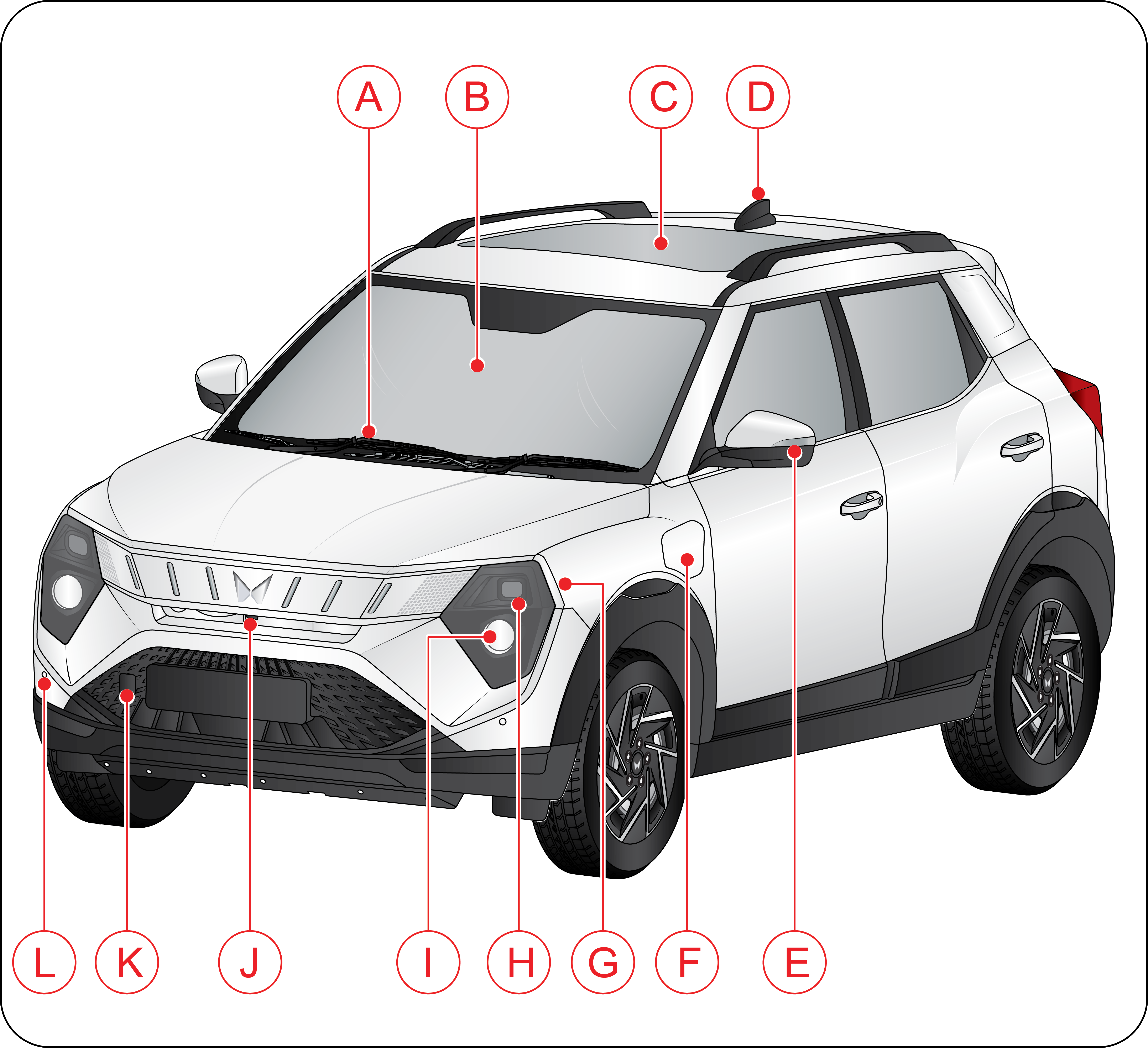
1.10 Front Overview
Graphic

A
Front Wiper
B
Front Windshield
C
Skyroof
D
Antenna
E
Outside Rear View Mirror (ORVM)/Side Repeater
F
Charging Port Lid
G
Daytime Running Lamp (DRL)/Turn Indicator
H
Head Lamp High Beam/Low Beam
I
Front Fog Lamp*
J
Front Camera*
K
Front Tow Hook
L
Front Park Assist Sensors (FPAS)*
* If Equipped
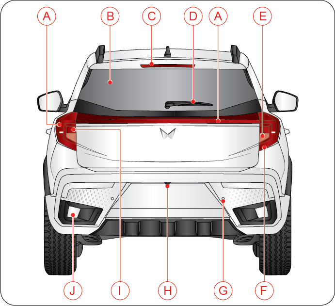
1.11 Rear Overview
Graphic

A
Tail Lamp
B
Rear Windshield / Demister*
C
High Mounted Stop Lamp (HMSL)
D
Rear Wiper
E
Reverse Lamp
F
Turn Signal Lamp
G
Reverse Parking Assist System
H
Rear View Camera
I
Stop Lamp
J
Reflector
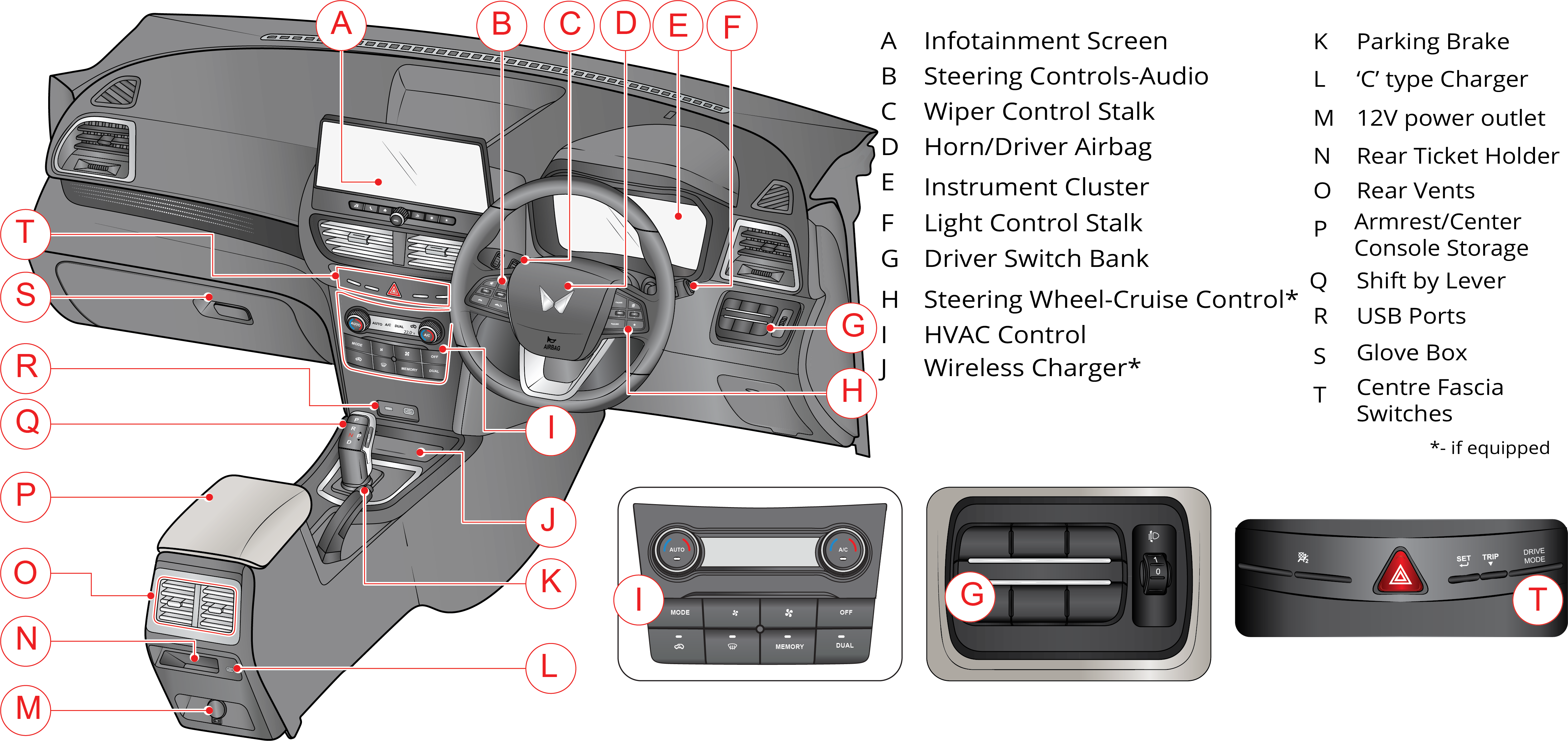
1.12 Instrument Panel Overview
Graphic
1.13 ADRENOX Connect
Graphic
The Adrenox connect mobile app provides information in your mobile phone about location and status of the vehicle and allows to control certain vehicle features in a secured way for both Android and iOS platform.
Kindly use the ADRENOX connect mobile app for connected car related features.
1.13.1 KYC (Know Your Customer) Registration
To activate connected car features including access to Adrenox mobile App, KYC process must be completed successfully.
•  Customer must produce valid mobile number, communication address and email ID for KYC registration. for registration purpose.
•  Preferred mobile number entered during the KYC process will be the login for Adrenox mobile app.
•  After successful KYC registration, customer must download the “ADRENOX connect” mobile application from Google Play store or iOS app store.
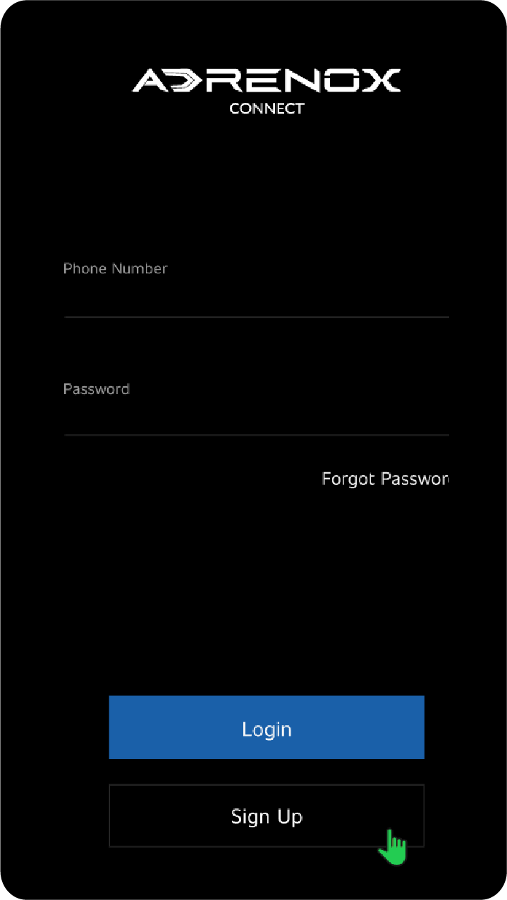
1.13.2 Login and Registration
Follow the below steps for Login and Registration:
Graphic
•  You can select sign up option from login page which redirects to sign up page.
•  Then enter registered Mobile number given in KYC form for connected services and click on Generate OTP.
•  OTP with a validity will be sent to the same mobile number.
•  If OTP is not received, you can request the OTP again by clicking on “Resend OTP”.
•  After entering valid OTP, click on “Verify My account”.
•  On successful verification you will be notified with a message “Account Verified”.
•  You will be directed to "Terms and Condition” with “I Agree” option on successful authentication.
1.13.3 Forgot / Change — Password / Pin
This Feature allows the existing user to change Password and change PIN.
In case user forgets the Password and PIN below flow helps to create PIN and password.
Forgot your password
In case you forget your password:
•  Tap on the Forgot Password? link from login page.
•  In forgot password page, enter the registered mobile number for connected services and click on Generate OTP.
•  Enter the OTP and click on Next button.
•  Enter New Password and Confirm Password and tap on Save button.
Change your password
To change your password on app, if you have already logged in:
•  Tap on the top Left corner from home screen.
•  Click on My Account and select Change Password.
•  Page will open with Old password, New password and Confirm password fields.
•  Fill all the required field and tap on save button.
1.13.4 ADRENOX Connect Features
FEATURE
DESCRIPTION
Alerts
Over Speed Alert
When your car exceeds the set speed limit. This speed limit value can be set under alert configuration in mobile application.
Lamp Status Alert
Alerts when vehicle park lamp left in ON condition while locking the vehicle Notifies when the vehicle park lamp is left in ON condition and helps to turn OFF remotely via mobile application.
Door Open Alert
Notifies when any of the doors open while vehicle is moving and also when you trigger for door lock and the door remains open unintentionally.
Geo-fence Alert
Alerts when your vehicle moves out of a set boundary area Helps you to create virtual boundary for any region and will be notified whenever your vehicle moves in or out of that boundary.
Time Fencing 
Notifies you when any movement of vehicle is detected during set time period.
Insurance Expiry
Suggests in advance to renew the Insurance as expiry date of Insurance approaches Notifies you in advance when the insurance is about to expire.
Route Deviation Alert
Alerts the user when the vehicle deviates from the pre-defined path.
Tyre Pressure Alert
Alerts on excessive/very low and high tyre pressure and navigate to nearby petrol station.
Personalized Safety Alert
Alerts the user via a personalized beloved ones voice prompt when the vehicle crosses the speed limit.
Pick-Up Reminder
Allows the user to create an event that reminds the user at the specified time.
Battery Charger Connect/Disconnect Alert
Alerts the user when the charger is connected and also when the charger is being disconnected from the vehicle.
Vehicle Start/Stop Alert
Notifies when normal vehicle start /stop event is detected.
Low Charge Alert
Alerts the user when there is a Low Charge (SOC is minimum) situation  in your mobile application. Helps you to nearby charging station.
Charge Complete Notification
Alerts the user when the charging has been stopped - fully charged, charger is plugged out or any other reason.
High Temperature Alert - HV Battery
Alerts the user when the High Temperature situation is identified and provides the option of roadside assistance to the user on the mobile application.
High Motor Temperature Alert
Alerts the user when the motor temperature is higher than the predefined limit and provides the option of roadside assistance to the user on the mobile application.
Charger Fault Alert (HV Battery Charger Malfunction Alert)
Alerts the user when there is a fault identified within the on-board charger and  provide the option of roadside assistance to the user on the mobile application.
EV Battery Warning (HV Battery Malfunction Alert)
Alerts the user there is a warning/fault is identified in the vehicle battery system.
Unauthorized Vehicle Entry Alert
Alerts the user when there was an unauthorized vehicle entry was attempted.
Driver Assistance
Geo-fence Based Campaigner
Allows the user to send campaigns based on the location of the vehicle.
Service Booking
Enables the users to book their service, through the M4U app.
My Documents (or) Document Wallet
Storage and retrieval of documents such as Driving license, Insurance.
Create Enquiry
Any Query / Enquiry about the product, Get info on Mahindra. Send an Inquiry on any car model. Dealers will get back to the customer on details.
Toll Diary / Toll Charge Assist
Enables the users with their FASTag recharge history. Enable the users to view total possible toll charge while planning the trip. Enables the users to recharge the FASTag.
Request App Access
Allows the user to share the vehicle access to two more users.
In Car Application
Just Dial
Allows the user to search for various services using the Just Dial app in the infotainment.
India Today
Allows the user to browse through news using India Today app in the infotainment.
Accuweather
Allows the user to view weather information using the Accuweather app in the infotainment.
Thrillophilia
Allows the user to search for amusement places and more using the Travel Advisor app in the infotainment.
Horoscope 
Allows the user to view daily fortune as per his/her zodiac sign.
Tickertape
Allows the user to check the market movement of their favorite stocks and indices.
Location Based Services
Share My Car Location
Share your car's location with friends and family.
Save Route / Save Place
Provision to save a route / place.
Pit Stops
Provides the users with the different pit stop option base don the location.
Push to Car
Allows the user to push routes/location from the mobile app to the vehicle.
About the Place
Provide the user with the details of the place, and the nearby attractions based on the journey plan.
Journey Planner
Allows the user to plan a journey by providing some basic information.
Live Tracking
GPS based vehicle tracking system for tracking vehicle’s location anywhere and at any point of time Helps to provide the real time vehicle location when vehicle is in movement Helps in sharing the vehicle location for a set time to your family and friends.
Read Vehicle Status
Check Door Status
Allows the user to view the current status of the vehicle door.
Check Lamp Status / Check Light Status
Allows the user to view the current status of the lamp.
Check ODO
Allows the customer to check the odometer of the vehicle.
Check Ignition Status
Allows the user to view the current ignition status of the vehicle.
Read Charging Status
Allows the user to view the current charging status of the vehicle.
Check Tiretronics Status
Allows the user to view the current status of tyre pressure.
Remote Vehicle Function
Remote Car Flashlight and Honking
Allows the user to remotely turn ON/OFF lights.
Remote Door Lock/Unlock
Provide access to the vehicle by remotely locking and unlocking the doors when vehicle is stationary.
Remote Lamp On/Off
Allows the user to remotely turn on or off the lamps using mobile app.
Find My Car / Locate My SUV
Allows the user to remotely locate the vehicle by turning on the lights.
Remote Sunroof Control
Allows the user to remotely open and close the sunroof using Adrenox app.
Remote Car Flashlight and Honking
Allows the user to remotely blink lights and honk to know the location of the vehicle in any space.
Safety
SOS
In case of SOS is initiated, SOS call will be triggered from vehicle, SMS will be sent to M4U and Emergency contacts along with the current vehicle location.
E-Call
In case of accident, Emergency call will be triggered from vehicle, SMS will be sent to M4U and Emergency contacts along with the current vehicle location.
Roadside Assistance
Allows the user to reach out for help in case of vehicle breakdown
Others
Weather Info
Provide the user with weather details based on the location.
Trip Tagging
Allows the user to tag a trip as either personal or official on the mobile app.
DND
Avoids distraction while driving by not pushing any AdrenoX Connect app notification when mobile is detected in the vehicle.
Contact Us
Allows the user to connect with the OEM through the customer care number available in the mobile app.
Trip History and Summary
Provides detailed information about the trips.
Over The Air Surprises
OEM Feature.
Service List Manager / Subscription Management
OEM Feature.
Personalized Greetings
Allows the user to set personalized greeting messages, which shall be played based on the user requirement.
Calendar Reminder
Allows the user to create time based/location- based events that remind the user at the specified time.
FOTA
OEM Feature.
Charge Assist (OCPI)
Allows the user to search, navigate to the nearest charging station and enables the perform all the activities related to the vehicle charging in a public charging station.
2 SEATS AND SAFETY
2.1 Seats
Sitting in Correct Position
Graphic
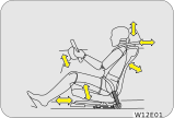
Follow the tips below for a comfortable and safe journey:
•  Sit in an upright position with the base of your spine pressed against the seat back.
•  The driver and front passenger seat head restraint has 6 positions. Adjust it as close as possible to the above specified position, with the top of the head restraint even with the top of your head.
•  Maintain at least a 25cm distance from the centre of the steering wheel to your chest.
•  The top curve of the steering wheel should align with your chin for ideal road visibility.
•  Adjust your seat and seat back angle such that your wrists rest on the steering wheel.
The seat should be adjusted while still maintaining control of the foot pedals, steering wheel (rest the wrists on the steering wheel) and your view of the instrument panel controls.
Never adjust the driver's seat while the vehicle is in motion. The seat movement may be more than expectation and cause the driver to unintentionally operate the accelerator or brake, or turn the steering wheel, causing loss of control of the vehicle, an accident or serious personal injury. Adjust the driver's seat only when the vehicle is stationary.
Never put objects under the seats. They may interfere with the seat-lock mechanism or unexpectedly activate the seat position adjusting lever, causing the seat to suddenly move, resulting in loss of control of the vehicle, an accident or serious personal injury.
While adjusting the seat, do not put your hands under the seat or near the moving parts. This may lead to injuries.
2.1.1 Front Seat
Front Seat Slide
Graphic
To move the seat forward or backward, pull and hold the seat slide lever up and move the seat to the desired position. Then, release the lever to lock.
While adjusting the seat, make sure the latch engages fully on both side of the fore-aft adjustment track rails and the seat is locked firmly in the desired position. An unlocked seat may move in a sudden stop or collision, causing injury to the person in that seat. Push and pull on the seat to ensure that it is locked.
Front Seat Recline
Graphic
To change the seat back angle, lean forward slightly and raise the lever. Then, lean back to the desired angle and release the lever. After adjusting, make sure the lever is returned to its original position and the seat back is locked.
The seat belts provide maximum protection in a frontal or rear collision when the occupants are sitting up straight and well back in the seats.
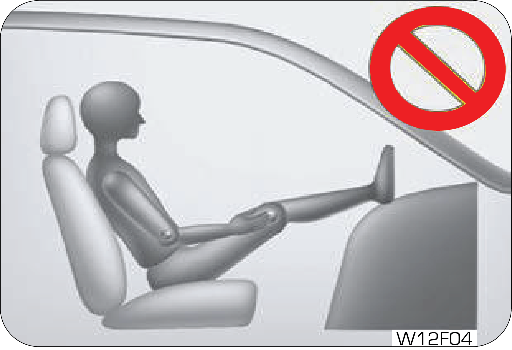
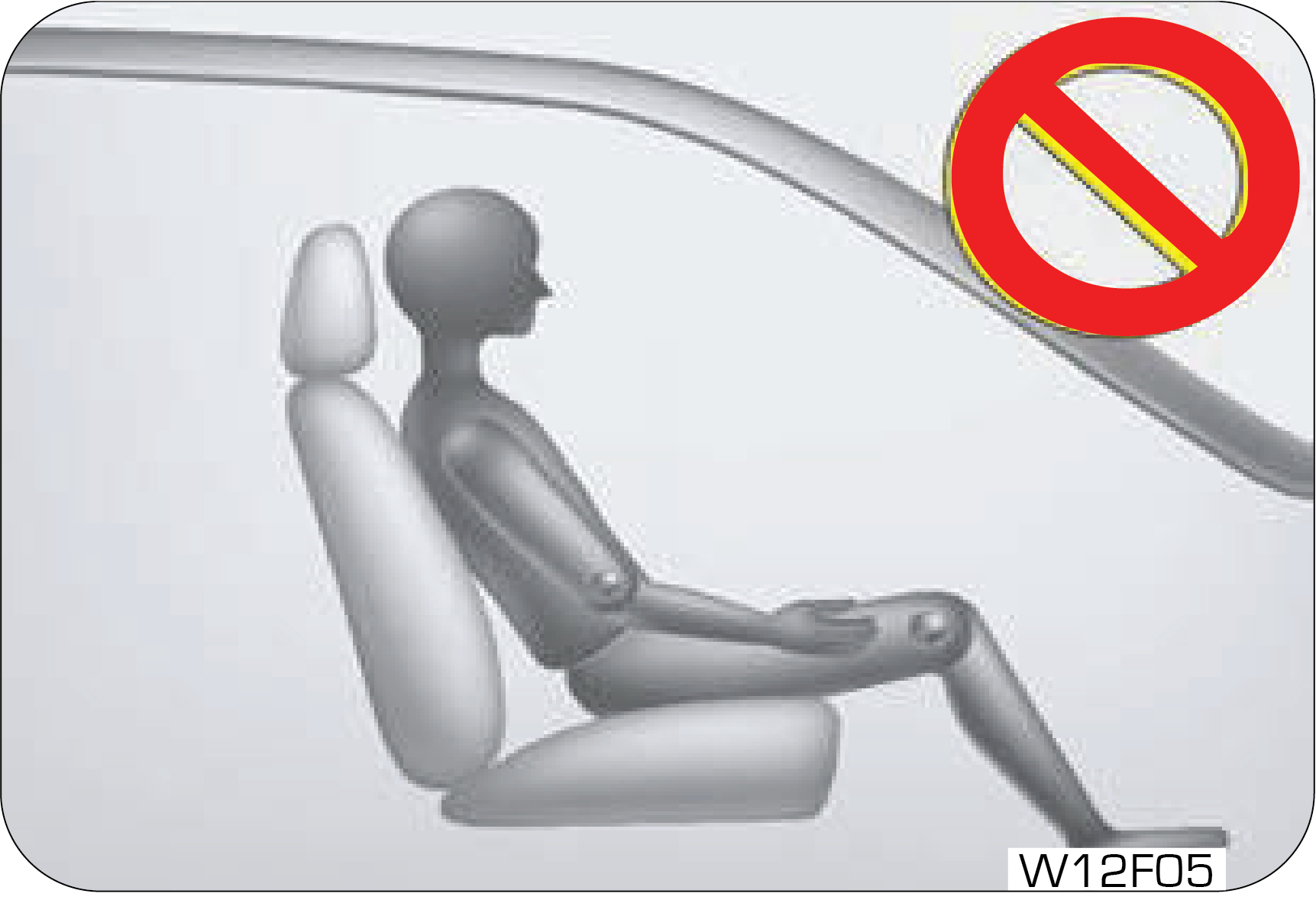
If you are reclined, the lap belt may slide past your hips and apply restraint forces directly to the abdomen, or the shoulder strap may contact your neck.
The more the seat is reclined, the greater the risk of serious injury.
When returning the rear-reclined seat back to its upright position, make sure you support the seat back while operating the lever.
Front Seat Height Adjustment
Graphic
The driver seat height can be raised or lowered with the help of height adjust handle.
To lower the seat cushion, push the lever down several times.
To raise the seat cushion, pull the lever up several times.
Do not adjust the height of seat while vehicle is moving.
2.1.2 Passenger Seat Recline
Graphic
To change the seat back angle, lean forward slightly and raise the lever. Then, lean back to the desired angle and release the lever. After adjusting, make sure the lever is returned to its original position and the seat back is locked.
The seat belts provide maximum protection in a frontal or rear collision when the occupants are sitting up straight and well back in the seats. If you are reclined, the lap belt may slide past your hips and apply restraint forces directly to the abdomen, or the shoulder strap may contact your neck. The more the seat is reclined, the greater the risk of serious injury.
When returning the rear-reclined seat back to its upright position, make sure you support the seat back while operating the lever.
2.1.3 Passenger Seat Slide
Graphic
To move the seat forward or backward, pull and hold the seat slide lever up and move the seat to the desired position. Then, release the lever to lock.
While adjusting the seat, make sure the latch engages fully on both side of the fore-aft adjustment track rails and the seat is locked firmly in the desired position. An unlocked seat may move in a sudden stop or collision, causing injury to the person in that seat. Push and pull on the seat to ensure that it is locked.
2.1.4 Rear Seat
Graphic
Graphic
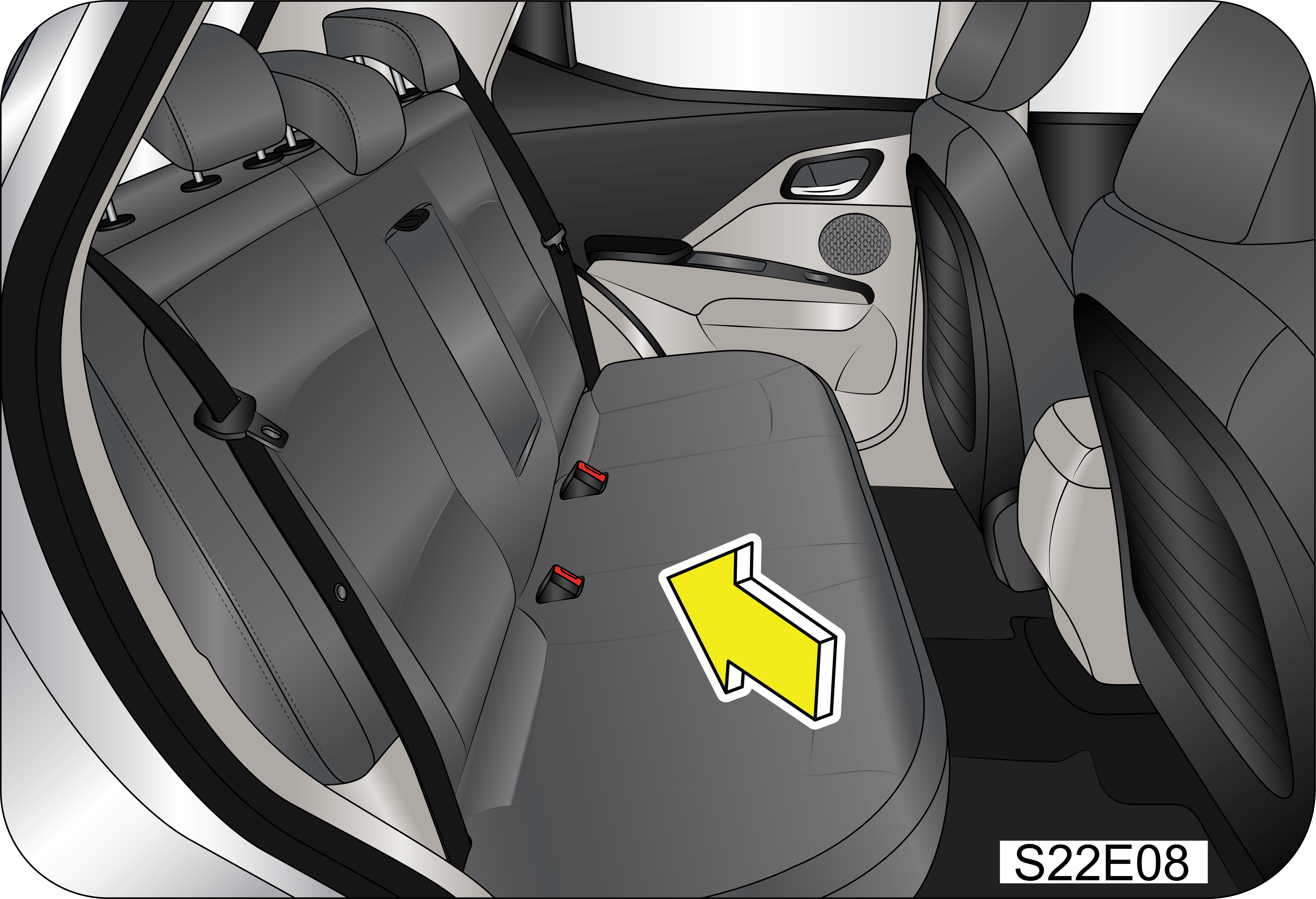
Second row bench seat is of 60:40 split configuration and also has a foldable armrest.
Folding The Rear Seat Back
To fold down the rear seat back:
•  Insert the rear seat belt buckle and belt webbing in the storage to prevent the seat belt from being damaged.
•  Lower the rear head restraints to the lowest position.
•  Release the seat back lock by pulling the release lever.
Graphic
When locking the rear seat back into upright position, make sure you hear “click” sound.
When the seat back is released from its holding latch, the seat back can completely be folded. Ensure that none of your body parts are trapped.
Graphic
Graphic
•  Fold the seat toward the front of the vehicle.
•  To use the rear seat, lift and pull the seat back backward. Pull the seat back firmly until it clicks into place. Make sure the seat back is locked in place.
Rear Seatback Holding Latch
Graphic
Graphic
Before returning the folded seat back to the normal position. Pull the rear seat belt out of the seat back so that the seat belt is not jammed with the holding latch.
•  Do not fold or unfold the rear seat when the vehicle is moving.
•  Make sure that there is nobody on the folded seat back and in cargo area.
•  If you place sharp or heavy objects on the seat back, there might be some damage to the seat backs or even to the seats.
•  Without completely lowering the second row head restraints or with excessively reclined front seat back, there may be some damage to the head restraints or the centre console if the second row seats are folded.
•  Take care that there are no objects placed on the rear seat cushion before folding the rear seat back down as any sharp features in the object may damage the seat cover.
•  All necessary driver’s seat adjustments should be made before driving.
•  Make sure that your seat is completely locked after adjusting.
•  Any object that might damage the seat should not be placed on the seat.
•  Removed or improperly adjusted head restraints can result in serious head and neck injuries in case of a collision. Make sure that the head restraints are in place and adjusted before driving.
•  Do not recline the seat back more than needed for comfort while vehicle is in motion. The seat belt is the most effective when the passenger sits back and straight up in the seat. If the seat back is reclined too much, then the risks of sliding under the lap belt and getting injured are increased.
•  Do not leave children unattended in parked vehicles. This can cause unexpected accident.
•  You can be hurt by the edges of the mechanism of the seat when trying to get the small objects (cigarette lighters, coins, credit cards) under the seat or caught between the seat and the centre console. Wear protective gloves to prevent injury.
•  Unexpected movement of the seat or seat back can cause loss of control.
•  Take care not to bother the passenger behind you when adjusting the seat position.
•  Sit upright in the centre of the seat and wear the seat belt around your hip and pelvic bones.
•  Do not place any objects in the path of seat back movement. Any obstruction in this path prevents the seat back from being locked, causing severe injuries or death during a collision.
•  Always raise the seat back to the proper upright position before driving.
•  Never drive the vehicle with the seat folded. In a collision, you will be seriously killed or injured as you lose the protection the seat belt can provide.
•  To avoid severe injuries and death during unexpected accidents, sit in such a way that the distance between the steering wheel and your chest at least 10 inches, as long as you are comfortable with driving.
•  Do not place a cigarette lighter on the floor or between the seats. The gas in the lighter container under the seat is potentially flammable when it is released from the container when the seat is moved.
•  Additional cushion between you and the seat cushion reduces the frictional force and could make you slide under the seat belt. This could result in serious injury or death.
•  Do not insert your hands under the seat or in the path of the seat movement when adjusting the seat. Your hands or fingers could get trapped between the seat and the frame.
•  Do not ride with the seat back reclined too much. You could slide under the seat belt in a collision, which could result in severe injury or death. Also, you cannot be protected by the seat belt and the belt can strangle you or even cut into your stomach. Therefore, sit up straight in your seat by keeping your seat back upright while driving.
•  When returning the seat back to the upright position, hold the seat back with your one hand and pull the release lever with the other hand. The more the seat back is reclined, the greater the restoring force of the seat back is. If you do not hold the seat back while adjusting the seat back, you could be injured by the restoring force.
2.2 Passenger Seat Head Restraint (If Equipped)
Graphic
The head restraint comprises the padded portion which contacts your head and is inserted/locked in receptacles on the top of the seat back.
Your vehicle seats are equipped with head restraints which are vertically adjustable. The purpose of these head restraints is to help limit head motion in the event of rear collision.
Always align top of the head restraint with the top of your head or as close to it as possible. To lower the head restraint, press the lock knob and push the head restraint down.
To raise the head restraint, pull it up without pressing the release button. To lower the head restraint, press the release button on top of the seat back and push the head restraint down.
Removed or improperly adjusted head restraints can result in serious head and neck injuries in case of a collision.
Do not apply excessive force to the head restraint during adjustment. It may get damaged.
If possible, place the centre line of the head restraint at the passenger’s eye level.
If the passenger is too tall or too short, adjust the head restraints to highest or lowest position.
2.3 Seat Belt
2.3.1 General Warnings and Instructions
At least once each month, inspect the seat belt webbing for any cuts, tears, or other signs of wear (such as fraying along the edges). Also inspect the anchors, retractors, and buckles to be sure they are tight and operational.
•  All occupants, including the driver, should always wear their seat belt no matter how short the trip in order to minimize the risk of severe injury in the event of a crash. In an accident, an un-belted passenger becomes a projectile, and can cause serious injury to himself or another passenger.
•  In a rollover crash, an un-belted person is significantly more likely prone to Injury than a person wearing a seat belt.
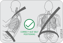
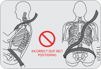
•  In order to be properly buckled, you must always sit up straight and keep your feet on the floor in front of you. The lap part must be worn low and tight across your hips, just touching the top of your thighs. While fastening the seat belt, the shoulder strap of the seat belt must pass over your chest and top of your shoulder. It must never touch your neck, face, the side of your shoulder, arm, or pass under your arm. The belt must always be flat against your body and not twisted in any way. Nothing, such as an arm rest, a pocketbook, or any external objects should be between you and the seat belt. Improperly worn of a seat belt will reduce the protection in an accident.
•  Seat belts should be adjusted as tightly as possible, consistent with comfort to properly secure the wearer in the seat.
Graphic
Graphic
•  The seat belts provided for your vehicle are designed for adults must be properly used and maintained.
•  For usage of adult seat belt to secure children, refer to section of manual for child seat positions and use a child restraint systems.
•  Passengers should not move out of or change seats while the vehicle is moving. Passenger who does not wear the seat belts will be under a high risk of thrown against the vehicle inside hard parts, against other occupants or out of the vehicle during emergency stop or collision.
•  Do not use any accessories on seat belts or modify in any way the seat belt system. Devices claiming to improve occupant comfort or reposition the seat belt can reduce the protection provided by the seat belt and increase the chance of serious injury in a crash.
•  An accident or emergency stop, can damage your seat belt system, even if the accident is “minor”. Please have your Authorized Mahindra Service Center inspect the seat belt system after an accident.
•  Please be aware that any unsecured item in your vehicle, such as your pet, unsecured child restraint system, a laptop or mobile phones, can become a projectile in the event of an accident or sudden stop, causing injuries to occupants in the vehicle.
Never use a damaged seat belt system. A damaged seat belt will not provide protection in an accident, resulting in serious injury.
•  Seat belt systems are prone to abuse. They are not indestructible. They must be handled with care to avoid damage.
•  Keep the belts clean and dry. Belt retraction may become difficult if the belts and webbings are soiled. If they need cleaning, use a mild soap solution or lukewarm water. Never use bleach, dye, or abrasive cleaners. These chemicals will severely weaken the belts.
•  Retractors in 3-point type seat belts retract the seat belts when not in use. The inertia lock and coil spring allow the belts to remain comfortable on users during normal driving. During accidents or abrupt stops, inertia locks restrict the sudden forward movement of the wearer.
Prevention of seat belt Slow retraction:
•  Check if there any twist on in-board or out-board side of safety belt.
•  Check if dust accumulated on outer parts such as Webbing, D-Loop, Tongue stopper and Tongue.
•  Remove the dust from D-Loop, Webbing, Tongue and Tongue stopper by compressed air or air blower.
•  Use clean and lint free cloth and hand gloves for cleaning safety belt parts D-Loop, Webbing, Tongue and Tongue stopper. Do not use any chemicals and cleaning fluids could damage the seat belt assembly.
•  Inspect the Webbing for retraction performance. Safety belt assembly cleaning required if seat belt retraction becomes very slow due to dust and soil accumulation on safety belt assembly, then below cleaning procedure to be followed:
1. Appropriate Procedure of disassembly of all pyrotechnic devices to be followed for pretensioner seat belt. The Battery terminal to be removed before disassembly of pretensioner, otherwise there will be error codes registered in Airbag ECU and Airbag ECU will show malfunction.
2. Open Pillar trims and take out Seat belt assembly on bench by carefully disassembly of connector and Lap Pretensioner/ Anchor wire assembly (if equipped). Kindly follow correct safety belt pretensioner handling procedure in case of pretensioner safety belts. Use clean and lint free cloth and hand gloves for cleaning safety belt assembly. Do not use any chemicals and cleaning fluids could damage the Seat belt webbing and other parts.
3. If seat belt movement is sticky due to dust accumulation. Then please contact the Authorized Mahindra Service Center for help in cleaning.
4. In case of soiling on the belt, use a mild soap solution consisting of 2 tablespoons of natural soap to 1 liter of lukewarm water.
5. Care to be taken to prevent contact of soap water with pretensioner.
6. Clean dust accumulated on D-Loop, Webbing and overall assembly by close inspection of D-Loop and Webbing using lint free cloth.
7. After cleaning safety belt they should be dried by lint free dry cloth.
8. After cleaning kindly inspect Webbing movement through D-Loop slot for any sticky movement of webbing.
9. Assemble the safety belt using correct torque. Re-assemble all trim parts.
10. Inspect the Webbing for retraction performance.
Seat Belts - Patients: Persons with serious medical conditions should also wear a seat belt. Consult your doctor for specific recommendations before travel.
Seat Belts - Pregnant Women: Pregnant women must also wear seat belts. Consult your doctor for specific recommendations.
Graphic
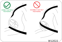
The lap belt should be worn snugly and as low as possible over the hips. The shoulder belt should be worn across your shoulder, but never across the stomach area. When worn properly, the seat belt will protect both the mother and the foetus in an accident or emergency stop.
A pregnant woman should never wear the seat belt across the stomach area. This could lead to serious injuries to the foetus and/or the pregnant mother.
Never wear twisted seat belts. Excessive forces will be transferred from the belt to the wearer, in a collision, resulting in serious personal injury.
Each seat belt is meant for use by one person only. Using one seat belt for more than one person at a time is dangerous. The seat belt will not be able to absorb the impact forces properly leading to serious injuries.
Never wear a belt around a child being carried on the occupant's lap. This could lead to serious injuries.
Seat Belt Usage is Necessary to:
•  Reduce the possibility of being out from your vehicle during an accident.
•  Reduce the possibility of injuries to upper body, lower body and legs during an accident.
•  Hold the driver in a position which allows better control of the vehicle.
Children who are too large for child restraint systems should always occupy the rear seat and use the vehicle seat belts. The lap portion should be snug fastened on the hips and as low as possible and the shoulder belt should be rout across the child's shoulder, not across neck or face. If you are unable to position the belt across the child's shoulder, the child should be seated in a booster seat. Frequently check the seat belt to be sure it remains snug and in position. A squirming child could cause the seat belt to come out of position.
2.3.2 Seat Belt Configuration
Graphic
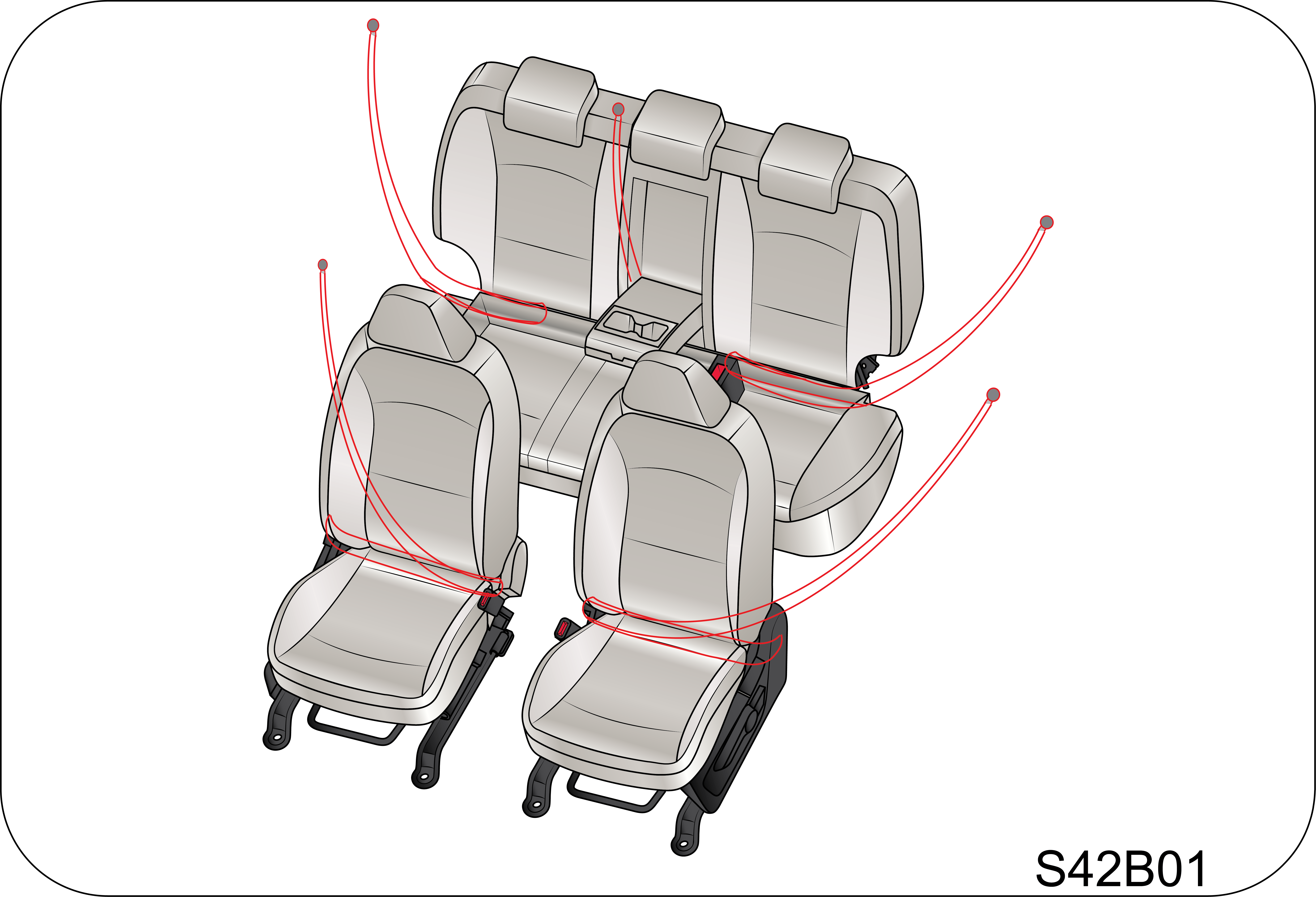
To protect you and your passengers in the event of an accident, it is highly recommended that the seat belts should be used by all occupants inside of your vehicle.
Seat Belt Types with respect to Location
Seat Location
Seat Belt Type
Driver Seat
Seat belt with Retractor Pretensioner and Load Limiter (RPLL)
Co-Driver Seat
Seat belt with Retractor Pretensioner and Load Limiter (RPLL)
2nd Row LH (40P)
Seat belt with Emergency Lock Retractor (ELR) for outboard occupant
2nd Row RH (60P)
Seat belt with Emergency Lock Retractor (ELR) for outboard and center occupant
Emergency Locking Retractor (ELR): The Emergency Locking Retractor (ELR) allows the driver seat belt to freely extend and retract with occupant movement, yet locks the belt during a sudden stop or upon impact.
Retractor Pretensioner and Load Limiter (RPLL): A pretensioner is designed to retract some of the webbing of a seat belt the instant a collision occurs, tightening the seat belt to restrain occupants quickly and reducing the amount they are thrown forward in a moderate or severe frontal crash.
Load limiters help protect occupants from seat belt-inflicted injury. In the event of a crash, the pretensioner restrains the occupant until certain amount of force is applied. At this point the load limiter releases the webbing gradually so as not to exert too much force on the chest of the occupant.
2.3.3 Seat Belt Pretensioner
In the event of a crash being detected, the belt pretensioner locks the seat belt by drawing back the seat belts on the driver’s and passenger’s torso and pelvis to prevent the driver and passenger being thrown forward. The seat belt pretensioner combined with the seat belt and airbag further increases safety.
Graphic
Its activation through Airbag ECU is signalled by pulling down of the metallic cable and removes slack in seat belt.
To obtain the highest degree of protection from the action of the pretensioning device, wear the seat belt on shoulder keeping it firmly close to the chest and bottom part of the seat belt on pelvis.
In case of side impact collisions, front air bags are not inflated, but seat belt pretensioners located in the same position with impact direction will be deployed together with side airbag.
Deployed seat belt pretensioners cannot be deployed again. Have the deployed seat belt pretensioners replaced by a Authorized Mahindra Service Center.
Operation of Pretensioner
Graphic
When a severe frontal impact occurs, seat belt pretensioners pull back the seat belts immediately to restrain the occupants to their seats.
Operation of load limiter
Graphic
After frontal collision, the load limiter releases the seat belt to prevent the occupant from being injured due to belt force.
Fastening the seat belt
Even if seat belts are not worn, the air bag will deploy in case of impact, collision triggered. In addition, airbags can protect occupants when the occupants are wearing their seat belts. Airbags may cause injuries to occupants if they do not wear or inappropriately use their seat belts.
•  Before driving, all occupants should fasten their seat belts. If not, the occupants can seriously be injured in a collision or sudden manoeuvring of the vehicle.
•  Sometimes you may have to apply strong force to pull the webbing out of the retract.
•  Each seat belt should be used by only one occupant at a time.
•  Seat belts and airbag’s can significantly minimise possible injury to occupants. But they cannot perfectly protect occupants from fatal collisions or injury.
•  Modifications and improper maintenance for the safety systems could cause serious injury. The safety systems including seat belts should be checked and repaired by only a Authorized Mahindra Service Center.
•  An infant or small child should always be restrained in an infant or child restraint.
2.3.4 Fastening the Seat Belt
Graphic
Graphic
Graphic
Adjust the seat as needed, sit up straight and well back in the seat. To fasten your seat belt, pull the webbing out of the retractor and insert the metal tab into the buckle. An audible “click” would be heard when the tab locks into the buckle. Pull up on the shoulder strap to tighten the lap belt across your hips. The seat belt retractor will pull in any slack in the shoulder strap. A slow and easy motion will allow the belt to extend and let you move your body around freely.
Periodically check the seat belt as you ride to be sure it remains snug and in position. If there is a sudden stop or impact, the belt will lock into position. It will also lock (restrict) if you try to lean forward too quickly.
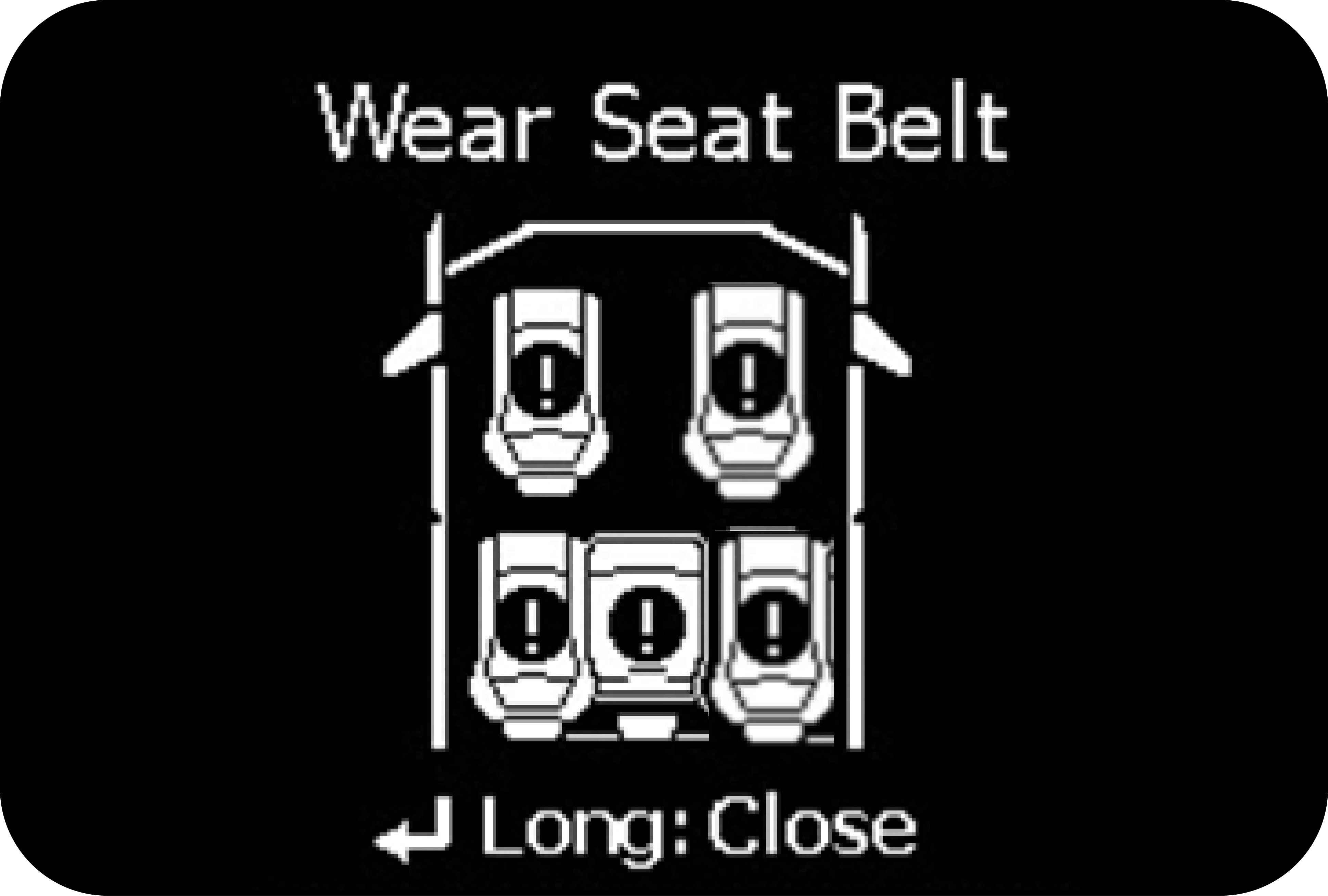
If the driver or co-driver seat belt is not fastened when the ignition is switched ON, the seat belt warning lamp illuminates and chimes beat will turn till seat belt fastened. Refer “Warning Lamps” in the “Instrument Cluster Features” chapter for further details.
2.3.5 Seat Belt Release
Graphic
To release the belt, press the buckle release button and allow the belt to retract. If the belt does not retract smoothly, pull it out and check for kinks or twists. Then make sure it remains untwisted as it retracts.
Never insert coins, clips, etc, in the buckle as this may prevent from properly latching the tongue and may cause damage to the buckle mechanism, thereby making the seat belt ineffective in an accident, resulting in serious personal injury.
2.3.6 Driver and Passenger Seat Belt Reminder Indication (If Equipped)
Graphic
The driver, front passenger and rear passenger seat belt reminder warning symbol lamp will be continuous ON in instrument cluster if driver or passenger doesn’t wear the seat belt and will be continuous until belt is buckled.
Chime will be activated when vehicle speed is more than 25 km/h of speed while vehicle is in motion which will be ON for 95 second for front seat belt and 35 second for rear seat belt.
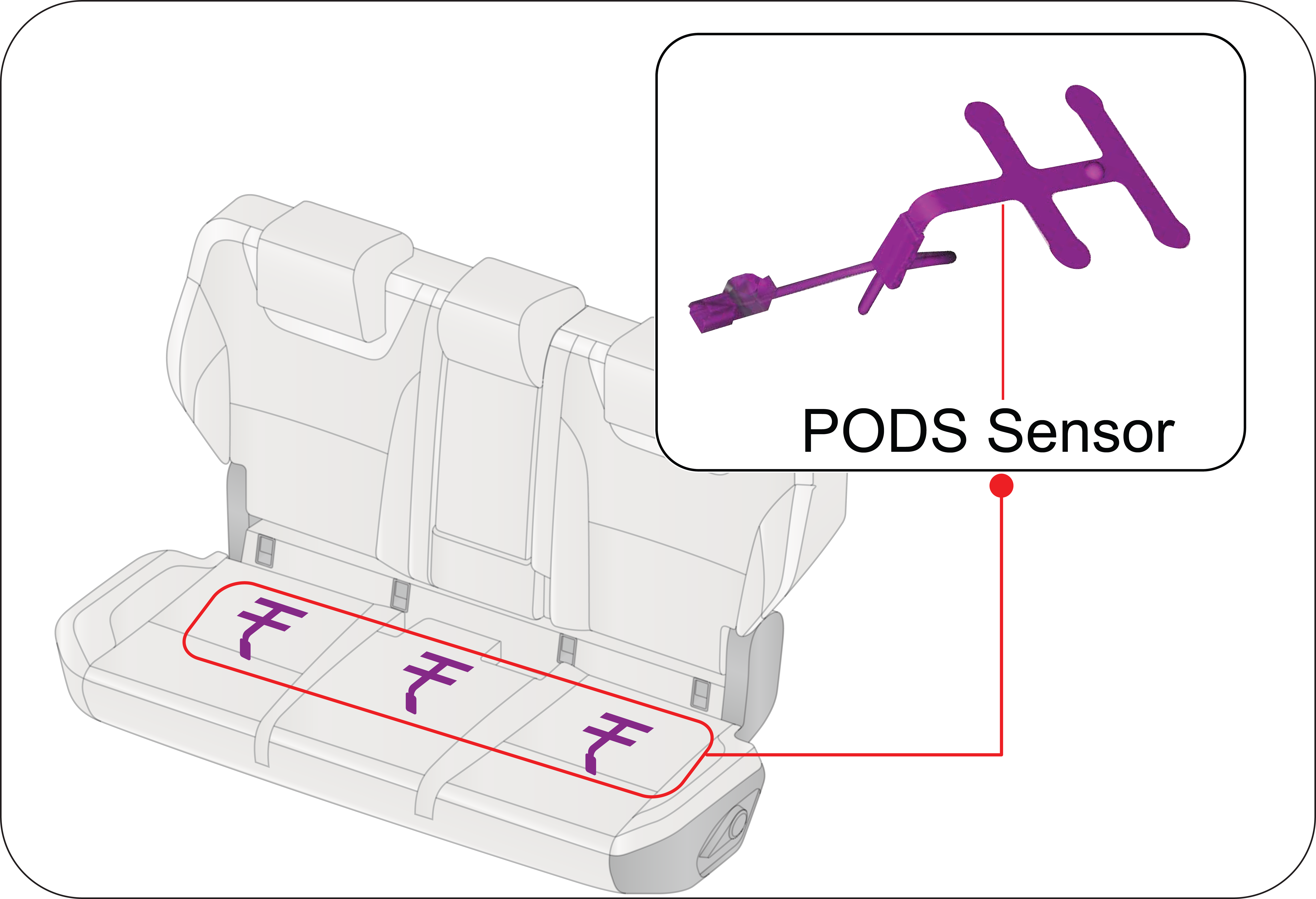
2.3.7 Passenger Occupant Detection System (PODS) and Seat Belt Reminder Indication
Graphic
Graphic
PODS detects the presence of occupant in the front passenger and on all rear seating locations.
Graphic
If Occupant is present on front passenger and rear passenger seats and not wearing the seat belt, seat belt reminder warning symbol lamp will glow on the vehicle instrument cluster panel and will be continuous until the seat belt is buckled.
It should be noted that the PODS require a minimum weight hence children may not be detected by PODS. Along with this warning symbol, a chime and alert in cluster will be ON for 95 second for front seat belt reminder and 35 second for rear passenger seat belt reminder.
Do keep in mind that after market seat covers also may deteriorate the occupant detection sensor performance, don’t use the non recommended/non authorized seat covers.
Graphic
Seat belt reminder warning lamp for passenger seat may glow in case of child is present in passenger seat.
Strong advice not to carry children in front seat without child restraint seat. Also do not use adult seat belt which is designed to harness person taller than 140 cms Always ensure Passenger Airbag is turn OFF before you carry child on passenger seat. We strongly urge that children should be in middle row using the child seats with the ISO FIX.
2.3.8 Seat Belt Height Adjuster
Graphic
You can adjust the height of the shoulder belt anchor for maximum comfort and safety of both front seats. If the height of the seat belt is too near your neck, you will not be getting the most effective protection.
The shoulder portion of the belt should be adjusted so that it lies across your chest and midway over your shoulder nearest to the door and not your neck.
To adjust the height of the seat belt anchor, lower or raise the height adjuster to an appropriate position while pressing the height adjuster button. Release the button to lock the anchor into position. Try sliding the height adjuster to make sure that it has locked into the position.
Adjust the shoulder belt height sitting well back in the seat. Do not adjust the seat belt height while vehicle is moving.
2.4 Infant and Child Safety
Graphic
Graphic
Graphic
Graphic
Table of Vehicle Handbook Information on Child Restraint Systems Installation Suitability for Various Positions
Mass group
Restraint device figure
Front Passenger (With ON/OFF Switch)
Rear out board
Rear Center
Mounting method of Child seat in vehicle
With Passenger Airbag ON
With Passenger Airbag OFF
Group 0: up to 10 kg (0 to 9 month)
Rear facing child seat
X
U
U
U
Rear facing seat using 3-point belt
Group 0+: up to 13 kg (0 to 2 year)
Rear facing child seat
X
U
U
U
Rear facing seat using 3-point belt
Group I: 9 to 18 kg (9 months to 4 year)
Rear facing/Forward facing child seat
X
U
U
U
Rear facing/Forward facing seat using 3-point belt
Group II: 15 to 25 kg (4 years to 6 year)
Booster seat
UF
U
U
U
Forward facing seat using 3-point belt
Group III: 22 to 36 kg (6 years to 12 year)
Booster seat
UF
U
U
U
Forward facing seat using 3-point belt
U: Suitable for “universal” category restraints approved for use in the mass group.
UF: Suitable for forward-facing “universal” category restraints approved for use in the mass group.
L: Suitable for particular child restraints given on attached list. These restraints may be of the “semi-universal” categories.
X: Seat position not suitable for children in the mass group.
Table of Vehicle Handbook Information on ISOFIX Child Restraint Systems Installation Suitability for Various ISOFIX Positions
Mass group
Size Class
Fixture
Vehicle ISOFIX Positions
Front Passenger
Rear Outboard
Rear Center
Carrycot
F
ISO/L1
X
X
X
G
ISO/L2
X
X
X
Group 0 up to 10 kg
E
ISO/R1
X
IL
X
Group 0+ up to 13 kg
E
ISO/R1
X
IL
X
D
ISO/R2
X
IL
X
C
ISO/R3
X
IL
X
Group I (9 to 18 kg)
D
ISO/R2
X
IL
X
C
ISO/R3
X
IL
X
B
ISO/F2
X
IUF/IL
X
B1
ISO/F2X
X
IUF/IL
X
A
ISO/F3
X
IUF/IL
X
Key of letters be inserted in the above table.
IUF: Suitable for ISOFIX forward child restraint systems of universal category approved for use in this mass group.
IL: Suitable for particular ISOFIX child restraint systems (CRS) given in attached list. These ISOFIX CRS are those of the “specific vehicle”, “restricted” or “semi-universal” categories.
X: ISOFIX position not suitable ISOFIX child restraint systems in this mass group and/or this size class.
Table of Vehicle Handbook Information on i-Size Child Restraint Systems for Installation in Various seating Positions
Restraint device figure
Front Passenger (With ON/OFF Switch)
Rear out board
Rear Center
With Passenger Airbag ON
With Passenger Airbag OFF
i-Size Child Restraint System
X
X
i-U
X
Key of letters be inserted in the above table
i-U: Suitable for i-Size “universal” Child Restraint System forward and rearward facing.
i-UF: Suitable for forward-facing i-Size “universal” Child Restraint System only.
X: Seating position not suitable for i-Size “universal” Child Restraint systems.
Anchorage Location
Graphic
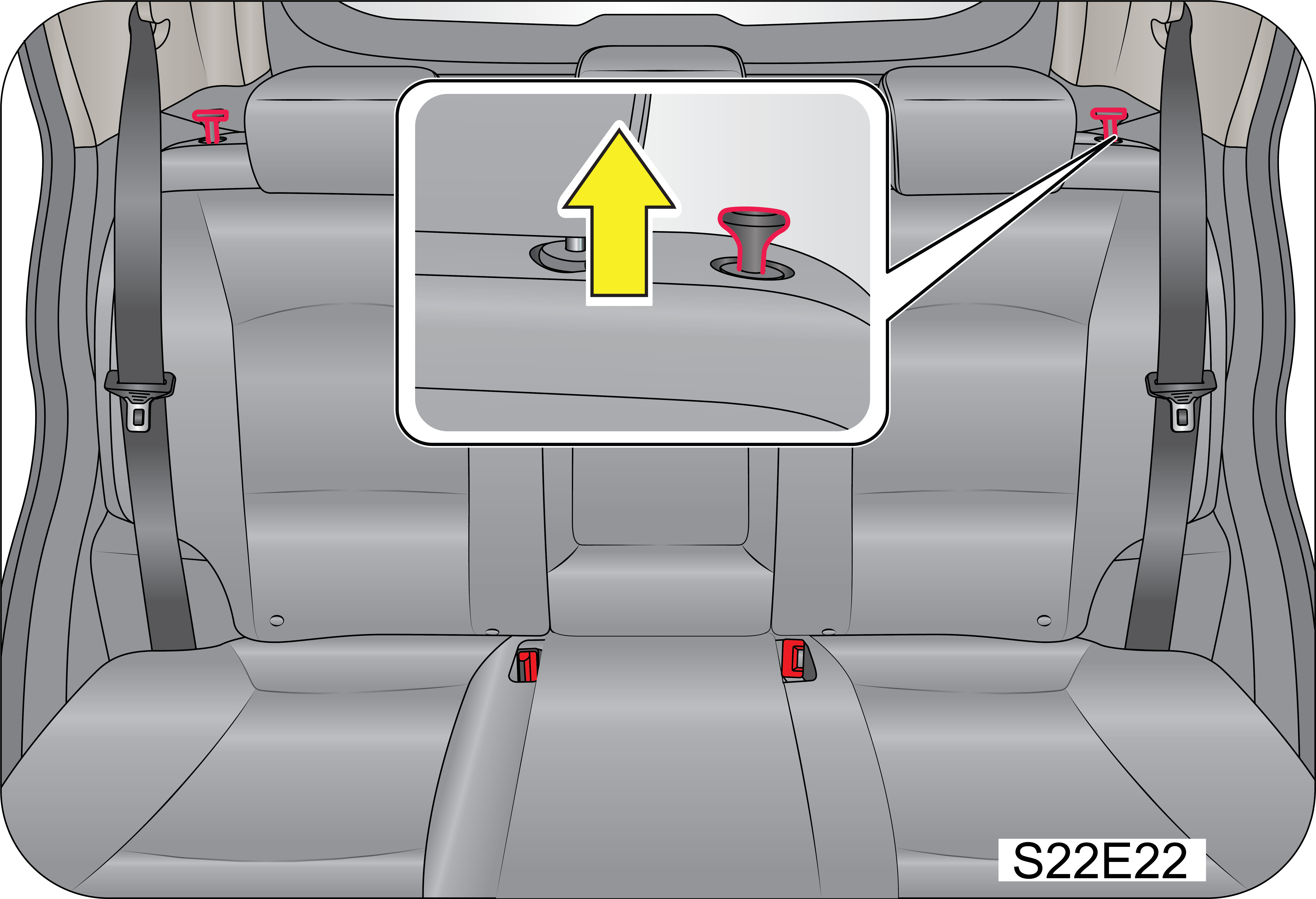
Child restraint anchor fittings are installed at the points as shown in the figure.
Graphic
Unrestrained infants and small children could be injured:
•  Never transport them unless they are properly restrained.
•  Use restrained system which meet safety standard.
•  Follow directions provided by the manufacturer.
2.4.1 Warning for Child Restraint
•  Use only the approved Child Restraint System (CRS) for better safety of your child.
•  Mahindra is not responsible for the personal injury and property damage due to the defect of child restraint system.
•  Use the proper type of child restraint system suitable for the weight and size for your baby.
•  Use the child restraint system at recommended seating location only and follow the instructions.
•  Child restraint has 5 categories based on the weight as below:
1
GROUP 0 : 0 ~ 10 KG
4
GROUP II : 15 ~ 25 KG
2
GROUP 0+ : 0 ~ 13 KG
5
GROUP III : 22 ~ 36 KG
3
GROUP I : 9 ~ 18 KG
   
•  Group 0 and 0+ : Rear-facing child restraint fitted on the rear seat (use of i–Size with Base and Support Leg is recommended).
•  Group I: Forward-facing child restraint fitted on the rear seat (use of i–Size and Top Tether is recommended).
•  Group II and III: Booster seat fitted on the rear seat with seat belt fastened. Always follow the installation procedure and use instructions provided by the manufacturer of the booster seat.
Recommended CRS
Child Age
CRS Make
CRS Type
Location
3 months to 4 Year old child
Britax Romer Dual Fix Pro M
i-SIZE
Rear Outboard
Cautions for i–Size Seat usage
•  The anchor provided on rear seat base back is the supplemental device to secure the child restraint system after engaging it by the lower latches. Therefore, do not secure the child restraint system only with the seat back anchors. The increased load may cause the hooks or anchors to break, causing serious injury or death.
•  If a child restraint is not properly secured to the vehicle and a child is not properly restrained in the child restraint, the child could be seriously injured or killed in a collision. Always follow the instructions provided by the manufacturer for installation.
•  Make sure the latches of the child restraint system are latched to the lower latches. In this case, you can hear the “click” sound and color indications.
•  The child restraint seat strap may not work properly if attached somewhere other than the correct seat back anchor provided on the rear seat base back side behind the seat carpet. Follow the instructions provided on the seat back for the details of anchor location.
•  Make sure that the child restraint system is firmly secured by rocking it in different directions.
•  Incorrectly installed child restraint system may cause an unexpected personal injury.
2.5 Supplemental Restraint System (SRS)
The Supplemental Restraint System (SRS) includes airbags, pre-tensioners and ECU. The airbags are designed to provide further protection to the vehicle occupants in addition to the primary protection provided by the seat belts and seat belt pre-tensioners.
The primary components of the system are the sensors which measure the crash severity. In the event of a significant frontal impact, the SRS airbags inflate to work in conjunction with the seat belts and help reduce injuries mainly to the driver's or front passenger’s head/chest.
Seat belts are the primary restraint system in the vehicle. An airbag provides supplemental protection in addition to the seat belts.
All occupants, including the driver, should always wear their seat belts irrespective of presence of airbag to minimise the risk of severe injury in the event of a crash.
Airbags are more effective in reducing injuries when the seat belts are worn.
Airbags
Your vehicle has the following airbags:
Graphic
A: Front Passenger Airbag
B: Driver Airbag
C: Two Side (seat) Impact Airbags (if equipped)
D: Two Curtain Airbags (if equipped)
2.5.1 Driver and Front Passenger Airbag
Your vehicle is equipped with a Supplemental Restraint System (Airbag) and lap/shoulder belts at both the driver and front passenger seating positions. The indications of the system’s presence are the letters “SRS AIRBAG” embossed on the airbag pad cover in the steering wheel and the passenger's side front panel pad above the glove box.
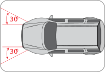
The SRS is designed to deploy the front airbag only when an impact is sufficiently severe and when the impact angle is less than ± 30° from the forward longitudinal axis of the vehicle.
Driver Airbag
Graphic
Graphic
Front Passenger Airbag
Graphic
Graphic
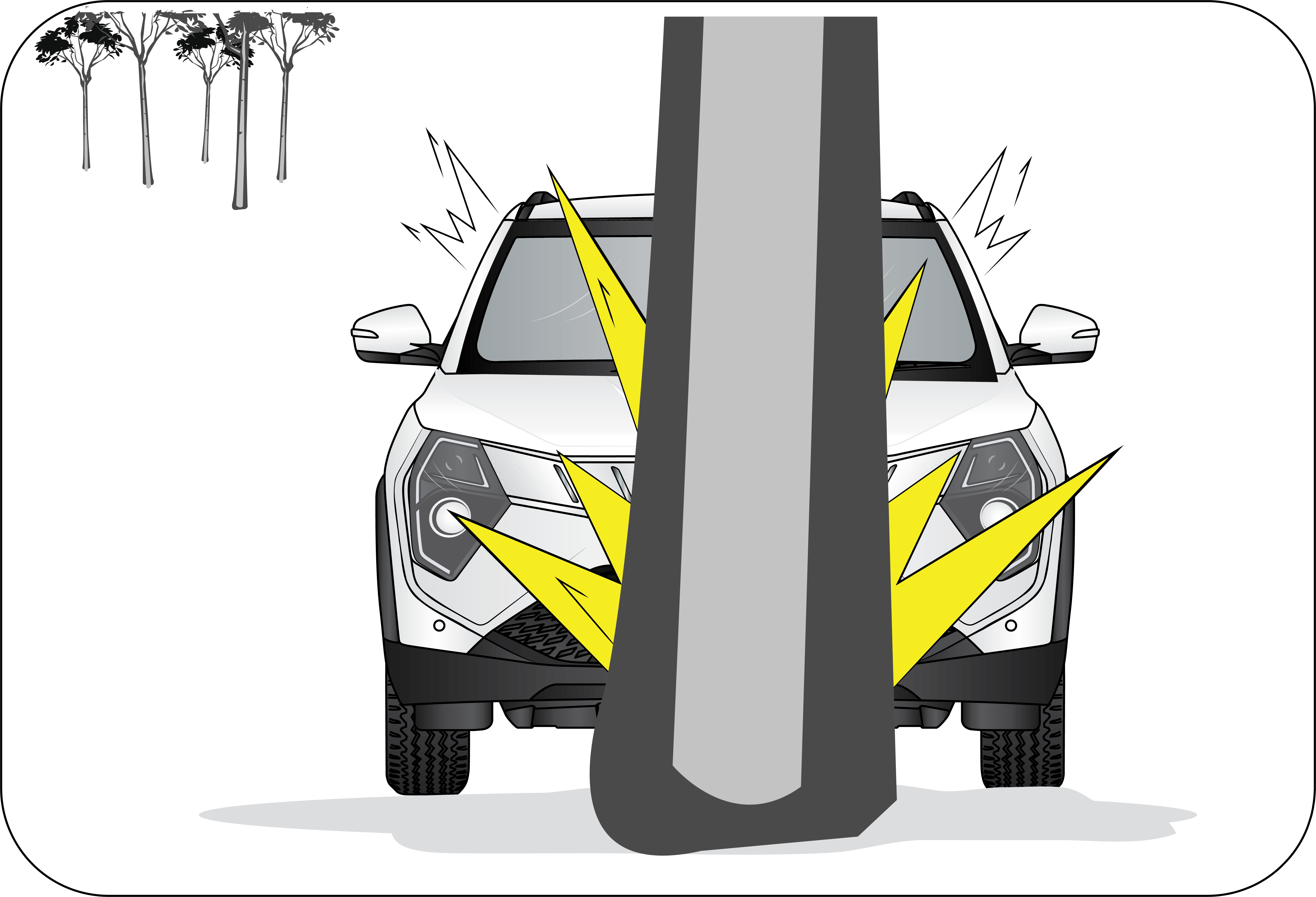
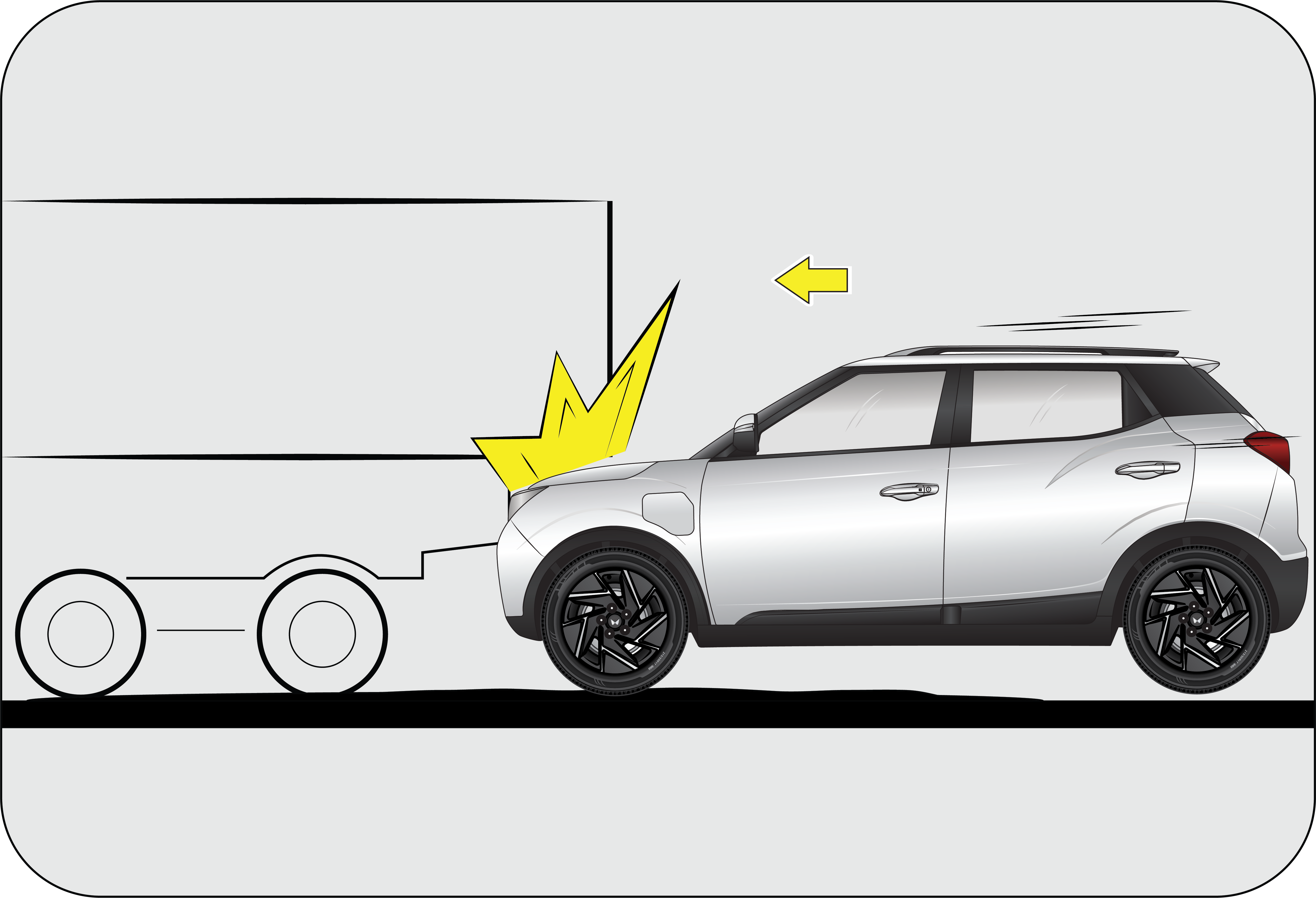
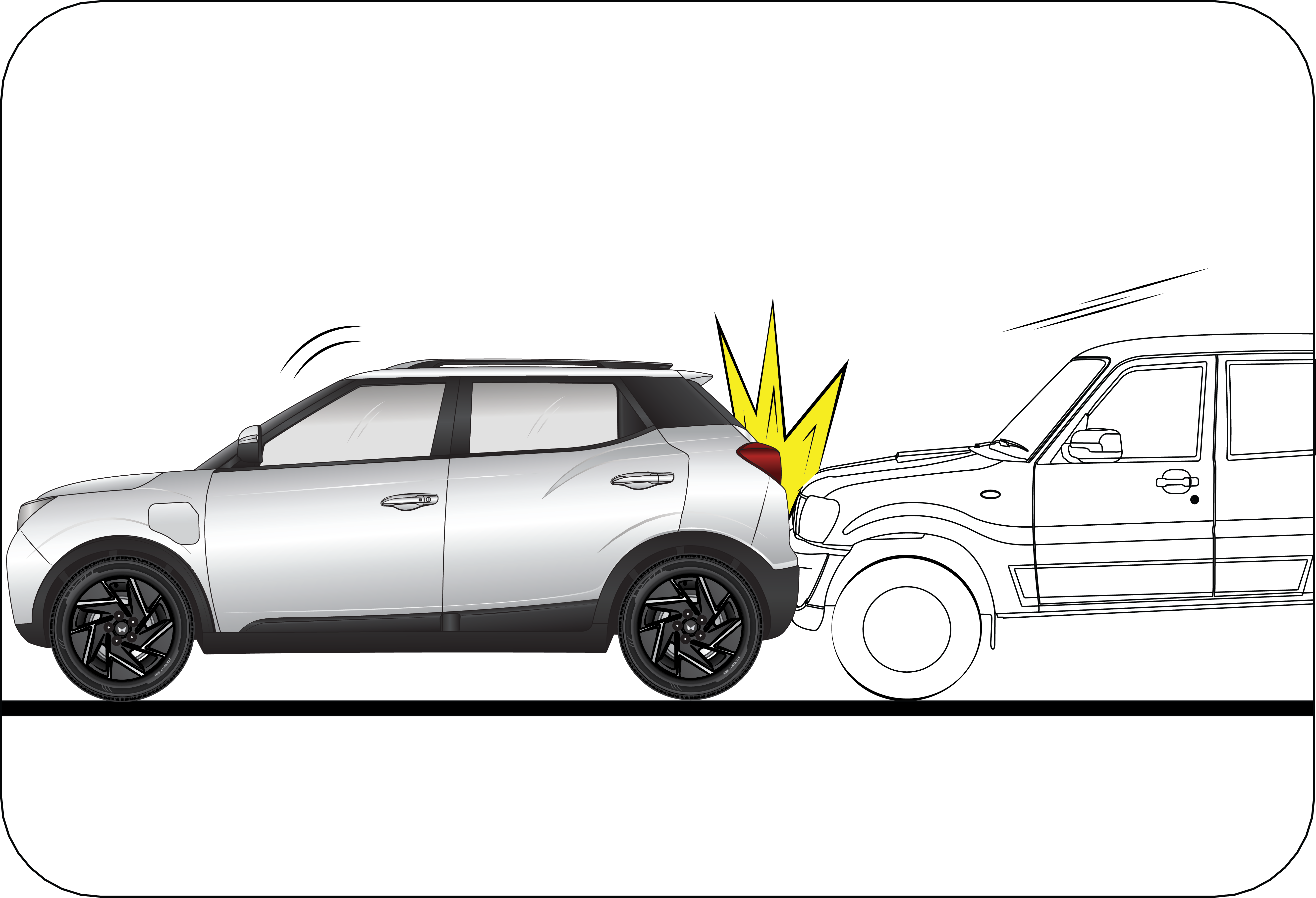
Front airbag are not intended to deploy in side-impact, rear impact or rollover crashes. In addition, front airbag will not deploy in frontal crashes which are below the prescribed deployment threshold where risk of serious injuries is low.
Do not place any objects over the airbag or between the airbag and yourself. It cause injuries.
2.5.2 Side Impact Airbag (If Equipped)
Graphic
Your vehicle is equipped with side impact airbag in both the front seats. The purpose of the airbag is to provide the vehicle's driver and/or the front passenger with additional protection during side impacts or collisions.
Graphic
Graphic
The side impact airbags are designed to deploy only during certain side-impact collisions, depending on the crash severity, angle, speed and point of impact. To minimise the risk of severe injury in the event of a crash, every passenger must always wear their seat belt (see the chapter on Seat Belts in this manual). The airbags inflate very quickly with great force. Do not position any part of your body too close to airbag, you or especially children could be seriously injured/killed by a deploying airbag.
•  In the case of a side collision, the curtain airbag may be deployed together with the relevant side airbag on the side the collision occurs.
•  The side impact airbag is supplementary to the seat belt systems and is not a substitute for them. Therefore, your seat belts must be worn at all times while the vehicle is in motion. The airbags deploy only in certain side impact conditions severe enough to cause significant injury to the vehicle occupants.
•  For best protection from the side impact airbag system and to avoid being injured by the deploying side impact airbag, all seat occupants should sit in an upright position with the seat belt properly fastened. The driver's hands should be placed on the steering wheel at the 9:00 and 3:00 positions. The passengers arms and hands should be placed on their laps.
•  Do not use any accessory seat covers. Use of seat covers could reduce or prevent the effectiveness of the system.
•  Do not install any accessories on the side or near the side impact airbag.
•  Do not place any objects over the airbag or between the air bag and yourself.
•  Do not place any objects (an umbrella, bag, etc.) between the door and the seat. Such objects may become dangerous projectiles and cause injury if the supplementary side impact airbag inflates.
Do not cover the front seats with anything. It hinders the air bag inflation.
An airbag is not designed to deploy in every type of crash. Depending on the type of accident or impact, the front airbags independently deploy thereby protecting the occupants. It is not necessary that ALL the airbags deploy during an accident.
2.5.3 Side Curtain Airbag (If Equipped)
The side curtain air bags are contained between right above the front and rear doors and the end of the vehicle roof.
The Side Curtain air bags are located along sides of the roof rails on the A and B pillars. They are designed to help protect the heads of the front seat occupants and the rear outboard seat occupants in certain side impact collisions. The curtain airbag are designed to deploy depending on the crash severity, angle, speed and impact. The curtain airbag are not designed to deploy in all side impact situations, collisions from the front or rear of the vehicle or in rollover situations.
Graphic
•  In the case of a side collision, the side airbag may be deployed together with the relevant curtain airbag on the side the collision occurs.
•  In order for side and curtain airbag to provide the best protection, both front seat occupants and outboard rear occupants should sit in an upright position with the seat belts properly fastened. Importantly, children should sit in a proper child restraint system in the rear seat.
•  When children are seated in the rear outboard seats, they must be seated in the proper child restraint system. Make sure to position the child restraint system as far away from the door side as possible, and secure the child restraint system in a locked position.
•  Do not allow the passengers to lean their heads or bodies onto doors or place objects between the doors and passengers when they are seated on seats equipped with side and/or curtain airbag.
2.5.4 Passenger Airbag Activation/Deactivation
Graphic
A: OFF/Deactivated
B: ON/Activated
The front passenger airbag is disabled (not inflatable) when placing the passenger airbag ON/OFF switch to “OFF” position. This switch is located on the left side of the instrument panel, and you can see it when opening the front passenger door. Press and turn this switch to operate.
Passenger Airbag OFF Indicator
Graphic
This indicator comes on when turning the passenger airbag ON/OFF switch to “OFF” position to disable the passenger airbag.
2.5.5 Airbag System Malfunction Lamp
Graphic
Airbags do not require any regular maintenance or service. The airbag system malfunction lamp illuminates when the ignition is ON, and it turns OFF after about two second as self check confirming normal operations of airbag system and malfunction lamp.
This lamp monitors airbag sensor assembly, airbag sensors, indicator lamp, seat belt pre-tensioner assemblies, inflators, interconnecting wiring and power sources.
If either of the following conditions occur, there is a malfunction of the airbags or seat belt pre-tensioner. Immediately contact a Authorized Mahindra Service Center.
•  The lamp does not glow when the ignition is switched ON or glows beyond six (6) second after switching the ignition ON.
•  The lamp comes ON at any other time, even briefly.
•  The lamp comes ON intermittently.
Never make any modifications to your vehicle which could affect the performance of airbag system. In particular, changes to the vehicle frame, bumpers, bull bar, front fenders, ride height, suspension, seat belts, interior trim, seats or steering wheel (especially covers, pads or other trim), could prevent proper deployment of the airbag. If you need to make any modifications to accommodate any disability you may have, please contact a Authorized Mahindra Service Center.
Never try to open or strike the airbag cover. If the airbag cover is cracked or damaged in any way, the airbag may not function as intended. Take the vehicle to a Authorized Mahindra Service Center.
Even if the airbags do not deploy during an accident, take your vehicle to a Authorized Mahindra Service Center for a thorough inspection of the airbag and seat belt systems, no matter how minor the accident. The airbag system could have been damaged, and may not work as intended in the future, resulting in serious injury.
2.5.6 Airbag Inflation/Deployment
The airbag sensors constantly monitor the forward deceleration of the vehicle. If an impact results in a forward deceleration beyond the designed threshold level, the system triggers the airbag inflators. This initiates a chemical reaction which quickly fills the airbags with non-toxic gas.
Upon deployment, tear seams moulded directly into the pad covers separate under pressure from the expansion of the airbags. Further opening of the covers allows full inflation of the airbags. A fully inflated airbag, in combination with a properly worn seat belt, slows the driver's or the passenger's forward motion, reducing the risk of head and chest injury.
After complete inflation, the airbag immediately starts deflating, enabling the driver to maintain forward visibility and the ability to manoeuvre or operate other controls.
Deployment of the airbags happen in a millisecond, producing a loud noise releasing a ‘white smoke’ and residue along with a non-toxic gas. This does not indicate a fire. This smoke may remain inside the vehicle for some time, and may cause some minor irritation to the eyes, skin or breathing. Be sure to wash off any residue with soap and water as soon as possible to prevent any potential skin irritation. Exit the vehicle as soon as possible after the accident.
Airbag deployment may cause windshield to break.
•  Do not modify, remove, strike or open the seat belt pre-tensioner assemblies, airbag sensor or surrounding area or wiring. Failure to follow these instructions may prevent them from activating correctly, cause sudden operation of the system or disable the system, which could result in serious injury.
•  Parts of the airbag module (steering wheel hub, airbag cover and inflator) may be hot for several minute after deployment. The airbags inflate only once.
•  Do not cover the steering wheel, instrument panel, seats with any object (e.g. dash panel covers, seat covers) which may prevent the airbags from inflating properly.
•  The airbags inflate with considerable force. While the system is designed to reduce serious injuries, primarily to the head and chest, it may also cause other, less severe injuries to the face, chest, arms and hands. These are usually in the nature of minor burns or abrasions and swelling, but the force of a deploying airbag can also cause more serious injuries, especially if an occupant's hands, arms, chest or head is in close proximity to the airbag module at the time of deployment. Sit straight and well back into the seat. Move your seat as far back as practical to allow room for airbag inflation, while still allowing you to properly operate/drive the vehicle.
The front passenger should never sit on the edge of the seat, stand near the glove compartment, rest feet or other parts of the body on the dashboard when the vehicle is moving.
Graphic
Graphic
The driver or front passenger who is too close to the steering wheel or dashboard can be seriously injured during airbag deployment.
Graphic
•  The driver must sit as far back as possible from the steering wheel while still maintaining control of the vehicle.
•  The front passenger must sit as far back as possible from the dashboard.
•  Sitting improperly or out of position can cause occupants to be shifted too close to a deploying airbag, strike the interior structure or be thrown from the vehicle resulting in serious injury.
•  Always sit upright with the seat back in an upright position, on the seat cushion centre with your seat belt on, legs comfortably extended and your feet on the floor.
•  All vehicle occupants must be properly restrained using the seat belts.
•  All infants and children must be placed in the rear seat of the vehicle in a child restraint seat and be properly restrained by seat belts.
•  Front airbags can injure occupants who are improperly positioned in the front seats.
•  Even with airbags, improperly belted and un-belted occupants can be severely injured when the airbag inflates. Always follow the precautions about seat belts, airbags and occupant safety contained in this manual.
•  Do not modify the front seats. Modification of the front seats could interfere with the operation of the supplemental restraint system or side impact airbags.
•  Do not place items under the front seats. Placing items under the front seats could interfere with the operation of the supplemental restraint system sensing components and wiring harnesses.
2.5.7 Child Restraint and Airbag
Do not use a rearward facing child restraint on a seat protected by an airbag in front of it.
In addition, do not place front-facing child restraints in the front passenger’s seat either. If the front passenger airbag inflates, it could cause serious or fatal injuries to the child.
This is indicated also on stickers that are located at the following position. On the front passenger’s sun visor.
Graphic
Graphic
Extreme Hazard! Do not use a rear-facing child restraint on a seat protected by an airbag in front of it!
Never put a child restraint in the front passenger’s seat. If the front passenger airbag inflates, it can cause serious or fatal injuries.
Never hold an infant or child on your lap. The infant or child could be seriously injured in the event of a crash. All infants and children should be properly restrained in appropriate child safety seats or seat belts in the rear seat.
Instal the child restraint system on the rear outboard seats, and securely lock the child restraint system in position with the help of ISOFIX.
Always Buckle Children (ABC) in the back seat. It is the safest place for children of any age to ride.
2.5.8 Airbag Deployment
The images shown in this section are for illustrative purpose only. They may not look like your model/variant or vehicle.
Front Airbag
Front airbag are designed to inflate in a frontal collision depending on the intensity, speed or angles of impact of the front collision.
Graphic
2.5.9  Airbag Non-deployment
Impacts below a pre-determined threshold level may not cause the airbag to deploy in the following cases:
Collision with Utility Poles or Trees :
Graphic
Airbags may not inflate if the vehicle collides with objects such as utility poles or trees, where the point of impact is concentrated to one area and the full force of the impact is not delivered to the sensors.
Frontal Impact :
Graphic
Frontal impact beyond 30° range from head-on to the vehicle.
Frontal Side Swipe Impact:
Frontal offset impact to the vehicle may not provide the deceleration force necessary for airbag deployment.
Graphic
In an angled collision, the force of impact may direct the occupants in a direction where the airbags would not be able to provide any additional benefit, and thus the sensors may not deploy any airbags.
Under-ride Situation:
Running under a truck's tailgate may not provide the decelerations necessary for airbag deployment.
Graphic
Airbags will not inflate in this “under-ride” situation where deceleration forces that are detected by sensors are significantly low.
Rear-end Collisions:
Graphic
Frontal airbags are not designed to inflate in rear collisions, where occupants are moved backward away from the airbags by the force of the impact. In this case, inflated airbags would not be able to provide any additional benefit.
Potholes or Stepped Surfaces:
Graphic
Driving into a big pothole, stepped surface or hitting the far side of a hole/incline will not inflate the airbag.
Rollover:
Graphic
Airbags will not inflate in rollover accidents where airbag deployment would not provide protection to the occupants. However, side impact and curtain airbags may inflate only when severe side impact causes rollover.
2.5.10 Airbag Service
Airbag Replacement: Self-servicing or tampering with the airbag system is dangerous. An airbag could accidentally deploy causing serious injuries, or will not deploy when there is a need. Always take your vehicle to a Authorized Mahindra Service Center for inspection and repairs.
Removing SRS Related Parts: We do not recommend removing the instrument panel, steering wheel, seats or airbag related parts or sensors by any individual or garages which are not recommended. Airbags could accidentally activate and cause serious injuries, or they may not deploy when there is a need. Visit a Authorized Mahindra Service Center if these parts must be removed.
Airbag Disposal: Improper disposal of an airbag or a vehicle with live airbags can be extremely dangerous. Approach a Authorized Mahindra Service Center to do these jobs.
Airbag Repair: If the front airbag cover or instrument panel airbag cover shows signs of damage or having been removed, the vehicle should be towed to the nearest Authorized Mahindra Service Center for repair. Do not attempt to self repair or reinstall the cover.
Airbag Maintenance: For cleaning the airbag covers/areas, use only a soft dry cloth or one which has been moistened with plain water. Solvents or cleaners could adversely affect the airbag covers and proper deployment of the system.
3 INSTRUMENT CLUSTER FEATURES
3.1 INSTRUMENT CLUSTER OVERVIEW
 
Graphic
A
State-of-Charge (SOC) Gauge
D
Time
G
Shift by Lever Mode
J
Range
B
Speedo Meter
E
Drive Info
H
Regen Meter/Power Meter
K
ODO Meter
C
Digital Speedo Meter
F
Outside Ambient Temperature
I
Efficiency Gauge
L
Drive Modes (FUN, FAST, FEARLESS)
3.1.1 Power/Regen Meter
Graphic
The meter needle in Power zone position indicates the power (in %) being used to drive the vehicle at that instance.
If the needle position is higher than zero (Power Zone), it represents that the battery power is being used by the system.
If the needle position is less than zero (Regen Zone), it represents that the regeneration is in progress.
During charging, needle stays in zero position.
3.1.2 Speedometer
Graphic
.
Graphic
The speedometer indicates the real-time road surface speed of the vehicle in km/h.
The digital speedo meter is included inside the gauge.
The vehicle speedometer is affected by size of the tyres used. If the size of the tyres are changed from those fitted at the factory, the speedometer might not display the correct road surface speed and distance travelled.
Over Speed Alert Buzzer
•  Primary level: Buzzer will trigger single chime in every 2 minutes when the vehicle speed reaches 80 km/h. once primary level chime is triggered, it will continue playing until speed is reduced to 76 km/h or goes beyond 120 km/h.
•  Secondary level: Buzzer will trigger periodic chime when the vehicle speed reaches 120 km/h and chime will continue playing until vehicle speed is reduced to 114 km/h. Below this speed primary level chime will be triggered and will continue till 76 km/h.
3.1.3 Odometer
Graphic
The odometer records and displays the total distance travelled in km.
3.1.4 State-of-Charge (SOC) Gauge
Graphic
The SOC indicates the current status of charge available in the HV batteries. This varies with changes in weather, load on battery and driving pattern.
The SOC will be displayed on a graph ranging from 0% to 100%, likely indicating the remaining battery charge. When the SOC drops below 17%, the display will show a red color, likely to warn the driver of low battery levels. If the SOC drops below 8%, the display will start flashing in red, signaling a critical low battery level and urging immediate action, such as charging the vehicle.
Small fluctuations in the SOC observed when the vehicle starts to move from stop condition is normal.
Soc bar change in dynamic, level changes from 0-100% and the same is displayed digitally.
3.1.5 Efficiency Gauge
Graphic
The efficiency gauge indicates energy consumption level during the drive. The higher the efficiency more bars on eco guage.
Bars will go up during regeneration.
Efficiency bar change in dynamic, level varies from lower efficiency to higher efficiency based on driving pattern.
3.2 Instrument Cluster screen flow
Graphic
3.2.1 Battery Info
In Battery Info, range will get displayed in screen.
Select Battery Info in screen by pressing respective switches. Refer “Instrument cluster screen flow” section for more details.
Graphic
Full in Charge
Full In Charge indicates the charge time which is required to charge the battery to 100% SOC in that particular charge cycle.
This varies based on the charger type and the power available for charging at that instance.
The full in charge screen shows when the vehicle is in charging.
When vehicle is not in charging condition average efficiency will be displayed.
Range: Range is the approximate distance that can be covered with the available charge.
Graphic
Range varies dynamically with respect to the driving pattern and Drive modes.
Use the range estimation as general guideline, this may not be same in the real road driving condition.
Use the time to charge information as the general guide line, it may vary based on ambient temperature, power source etc.
3.2.2 Trip Meter
Graphic
Range is the approximate distance that can be covered with the available charge.
Select TRIP A / TRIP B in screen by pressing Up/Down switch in steering wheel switch. Long press of OK switch will reset trip information, average speed and driving time.
Beyond the maximum value of the trip meter, it will reset to zero.
Trip A
Trip B
Min
Max
Min
Max
0
9999.9
0
9999.9
It is recommended to reset the trip meter when battery is disconnected and reconnected.
3.2.3 Clock Screens
Graphic
The time on the clock and date is in sync with the infotainment. Any change in infotainment will reflect on the cluster. Refer settings for changing clock type.
3.2.4 Outside Ambient Temperature
Graphic
This screen shows the outside ambient temperature.
Units change is in sync with Infotainment.
3.2.5 Cluster Setting
Cluster Setting can be accessed by pressing MENU button in Steering wheel.
Use Enter button to select the setting option.
Cluster will display the Setting information.
Graphic
3.3 Drive Information
In Drive Information, Drive Time and Average Speed will get displayed in screen.
Select Drive Information in screen by pressing respective switches. Refer “Instrument cluster screen flow” section EC and EL variants for more details.
Graphic
Drive Time
Drive Duration is the elapsed time from the start of this trip cycle.
Graphic
Average Speed
Average Speed is calculated based on the total distance covered and time taken from the start of this trip cycle.
Graphic
Gear Indicator
Gear indicator displays the actual engaged gear in the vehicle.
Graphic
Drive Summary
Gear indicator displays the actual engaged gear in the vehicle.
3.4 Navigation
Navigation can be accessed by pressing MENU button in steering wheel.
It displays data related to map view which is displayed in infotainment.
Use OK button to enter Navigation page.
Cluster will display the Navigation information.
Like Turn By Turn Navigation and Full / Partial Map view from native navigation.
Full Screen Navigation
Partial Screen Navigation
Graphic
Graphic
To enter full navigation if you are at partial Navigation screen, long press the OK switch to view full map.
3.5 Driver Assistance (If Equipped)
Graphic
1. Navigate to Setting menu using MENU button.
Graphic
2. Press OK to enter setting. Press Up/Down button to navigate to Driver Assistance option.
Graphic
3. Press OK to enter Driver Assistance option. Use Up/Down button to navigate driver assistance features and press OK button to select the corresponding feature options.
Graphic
4. Use Up/Down button to navigate to the options and press OK button to select the corresponding option.
Above procedure is applicable for all other Driver Assistance features.
Refer to Advanced Driver Assistance System chapter for more details.
3.6 Driver Assist (ADAS) (If Equipped)
Graphic
Driver Assistance can be accessed by pressing MENU button in Steering wheel switches.
Use OK button to enter Drive page.
Driver Assistance Menu View
Non Driver Assistance Menu View
Graphic
Graphic
Long press up button shall enter into LKAS setting (if equipped).
Refer “Advanced Driver Assistance System” chapter for more details.
Cluster will display the below features in Driver Assistance Menu:
1. Adaptive Cruise Control (ACC)
2. Collision Mitigation System
•  Auto Emergency Braking System (AEBS)
•  Front Collision Warning (FCW)
3. Lane Keep Assist System (LKA/LDW)
•  Lane Keep Assist (LKA)
•  Lane Departure Warning (LDW)
4. Smart Pilot Assist System (SPA)
5. High Beam Assist System (HBA)
6. Traffic Sign Recognition (TSR)
7. Front Vehicle Start Alert (FVSA)
8. Speed Limit Assist (SLA)
3.7 Vehicle Condition Related Warning
Below alerts come for 5 seconds when the conditions are met:
Display
Operating Conditions
Graphic
This message comes when brake fluid level is low while driving.
Graphic
This message comes when scheduled service is due.
Graphic
This message comes on when the park lamps are ON and ignition is turned OFF.
Graphic
This message comes when passenger airbag switch is turned OFF.
Graphic
This message comes on when the ESC system is faulty, and the vehicle has been running.
Graphic
This message comes when cruise mode is turned ON manually using switch.
Graphic
This message comes when cruise mode is turned OFF manually using switch.
Graphic
This message comes when Cruise Standby mode is enabled while driving.
Graphic
This message comes when either of driver or passenger (if occupied) seat belt is unbuckled.
Graphic
This message comes when you are driving vehicle above 120 km/h.
Graphic
This message comes when you try to move the vehicle when park brake is still engaged.
Graphic
The message will be displayed if Auto Light function is turned ON.
Refer “Head Lamp Auto Function” in Convenience System 1 chapter for further details.
Graphic
The message will be displayed if Auto Light function is turned OFF.
Refer “Head Lamp Auto Function” in Convenience System 1 chapter for further details.
Graphic
The message will be displayed if Auto Wiper function is turned ON.
Refer “Auto Mode” in Convenience System 1 chapter for further details.
Graphic
The message will be displayed if Auto Wiper function is turned OFF.
Refer “Auto Mode” in Convenience System 1 chapter for further details.
Graphic
This alert is displayed when Sunroof is left open at ignition off.
Graphic
The alert is displayed when ignition is off, driver door is open and the driver has forgotten their phone in the wireless charging tray.
3.8 Alerts
Alert Display
Conditions
Alert Status
Telltale Display
Telltale Status
Graphic
This alert comes when there is a fault observed during the charging process that prevents charging.
Alert comes only for 5 seconds with chime.
Applicable in both ignition ON/OFF state.
Graphic
Continuous ON (applicable if the fault de-rates performance).
Graphic
This alert comes when the vehicle charging is completed.
Alert comes only for 5 seconds with chime.
Applicable in both ignition ON/OFF state.
   
Graphic
This alert comes when the vehicle charging is interrupted because of user intervention or power supply is lost.
Alert comes only for 5 seconds with chime
Applicable in both ignition ON/OFF state.
   
Graphic
This alert comes when radiator fan or EPT cooling system malfunction.
Alert comes only for 5 seconds with chime.
Applicable in ignition ON state only.
Graphic
Continuous ON
Graphic
Continuous ON/Blinking (if temperature goes beyond threshold)
Graphic
This alert comes, when there is a battery related malfunction or EPT components malfunction, and the vehicle enters into de-rated mode
Alert comes only for 5 seconds with chime.
Applicable in ignition ON state only.
   
Graphic
This alert comes, when the vehicle is not drivable because of EPT Components or battery related malfunctions.
Alert comes only for 5 seconds with chime.
Applicable in ignition ON state only.
Graphic
Continuous ON
Graphic
This alert comes, when vehicle speed is ≥ 10 km/h and SOC<10 %
Alert comes only for 5 seconds with chime.
Applicable in ignition ON state only.
   
Graphic
This alert comes, when the user is trying to insert the charging gun, but the gun is not fully inserted into the vehicle.
Alert comes only for 5 seconds with chime.
Applicable in both ignition ON/OFF state.
   
Graphic
This Alert comes when both brake & accelerator pedals input are detected during drive enable request or gear shift request (Refer “Shift Lever” section for more details).
Alert comes only for 5 seconds with chime.
Applicable in ignition ON state only.
   
Graphic
This alert comes, when a charge gun is connected and the user triggers the drive enable request.
Alert comes only for 5 seconds with chime.
Applicable in ignition ON state only.
Graphic
Continuous ON
Graphic
This alert comes, when charging gun is connected to vehicle and the main power is not turned ON.
Alert comes only for 5 seconds with chime.
Applicable in ignition ON state only.
   
Graphic
This alert comes when HV battery SOC < 20%.
Alert comes only for 5 seconds with chime.
Applicable in both ignition ON/OFF state.
   
Graphic
This alert comes when SOC <10%, and vehicle goes in to de-rated mode.
Alert comes only for 5 seconds with chime.
Applicable in both ignition ON/OFF state.
   
Graphic
This alert comes when parking brake is not engaged during charging
Alert comes only for 5 seconds with chime.
Applicable in both ignition ON/OFF state.
   
Graphic
This alert comes in non-PKE variant--> when ignition is ON with gear is in Park/Neutral position and brake pedal is pressed.
Alert comes only for 5 seconds with chime.
Applicable in ignition ON state only.
   
Graphic
This alert comes in PKE variant--> when ignition is ON with gear in Park/Neutral position and brake pedal is pressed.
Alert comes only for 5 seconds with chime.
Applicable in ignition ON state only
   
Graphic
This alert comes, when user is trying to shift gear in ignition ON without pressing brake pedal or while driving, gear shift is tried without brake press (Refer “Shift Lever” section for more details).
Alert comes only for 5 seconds with chime.
Applicable in ignition ON state only.
Graphic
Continuous ON
Graphic
When this alert is being displayed, stop the vehicle and immediately get out and move away. Contact an Authorized Mahindra Service Center immediately.
Alert will be ON continuously with chime.
Applicable in ignition ON state only.
Graphic
Continuous ON
 
Graphic
This alert comes, once the drive enable process is successful and the vehicle is ready to drive.
 
Graphic
Continuous ON
Graphic
This alert indicate that there is a fault related to Non-EPT components. Contact an Authorized Mahindra Service Center for assistance.
 
Graphic
Continuous ON
3.9 Drive Mode Control Alerts
Display
Operating conditions
Graphic
Fun Mode Activated: This message will come for few seconds when the user is selecting “Fun Mode” using center console switch. Refer “Drive Mode Control” section for more details.
Graphic
Fast Mode Activated: This message will come for few seconds when the user is selecting “Fast Mode” using center console switch. Refer “Drive Mode Control” section for more details.
Graphic
Fearless Mode Activated: This message will come for few seconds, when the user is selecting “Fearless Mode” using center console switch. Refer “Drive Mode Control” section for more details.
Drive mode indication will always be available in cluster information screen bottom of the speedometer.
3.10 Smart Key Alerts
Refer PKE section of the owner’s manual for more details
Display
Operating Conditions
Graphic
The warning will be triggered when key is inside the vehicle and you try to do passive lock operation.
Graphic
The warning will be triggered when vehicle is in ignition ON condition, door status is changed and key is not inside the vehicle.
Graphic
The warning will be triggered when start/stop switch is stuck for more than 60 seconds.
Graphic
The warning will be triggered when key fob battery is low and user need to keep the key fob in the armrest pocket and then press the start/stop switch to turn ON the vehicle.
Graphic
The warning will be triggered when key fob battery is Low.
3.11 Steering Lock Alerts
Display
Operating Conditions
Graphic
This is a temporary malfunction of ESCL and the message is displayed if steering wheel has to be rotated while ignition is being turned ON.
Alert comes only for 5 seconds with chime.
Application in both ignition ON/OFF state.
Graphic
This warning is displayed when ESCL is not learned. Contact an Authorized Mahindra Service Center for assistance.
Alert comes only for 5 seconds with chime.
Application in both ignition ON/OFF state.
Graphic
The message is displayed if the system check-up is required since the ESCL system is malfunctioning. Contact an Authorized Mahindra Service Center for assistance.
Alert comes only for 5 seconds with chime.
Application in both ignition ON/OFF state.
Graphic
This is a temporary malfunction of ESCL and the message is displayed if the steering column is not locked. Rotate back & forth, then release the steering wheel while trying to turn ignition OFF.
Alert comes only for 5 seconds with chime.
Application in both ignition ON/OFF state.
3.12 Gear Shift Alerts
Display
Operating Conditions
Graphic
This alert comes when the park switch, or shift unlock button is pressed for more than 60 seconds or when there is a gear shifter malfunction. In such cases contact an Authorized Mahindra Service Center for assistance.
Graphic
This alert comes when,
1. Vehicle is moving in reverse direction (speed > 5 km/h) and if the driver tries to move the gear shifter lever to the “D” position with the brake pedal and shift unlock button pressed.
2. The vehicle is moving in the forward direction (speed > 5 km/h) and if the driver tries to move the gear shifter lever to the “R” position with the brake pedal and shift unlock pressed.
Note: In both the cases, neutral gear will be engaged.
Graphic
This alert comes when,
1. Vehicle is moving in the reverse direction (speed > 2 km/h) and if the driver presses “P” button to engage the “Park” mode with brake pedal pressed.
2. Vehicle is moving in the forward direction (speed > 2 km/h) and if the driver presses “P” button to engage the “Park” mode with brake pedal pressed.
Graphic
This alert comes, when the gear shifting is not possible as brake pedal press precondition is not met. Refer “Shift Lever” section for more details.
Graphic
This alert comes, when the gear shifting is not possible as shift unlock button press precondition is not met. Refer “Shift Lever” section for more details.
Graphic
This alert comes when the park switch is depressed for more than 30 seconds.
Graphic
This alert comes when the shift unlock button is depressed for more than 30 seconds.
3.13 Door Open Alerts
Display
Operating Conditions
Graphic
Passenger door is open.
Alert comes with animation.
Graphic
Driver door is open.
Alert comes with animation.
Graphic
Hood is open.
Alert comes with animation.
Graphic
Rear door (LH) is open.
Alert comes with animation.
Graphic
Rear door (RH) is open.
Alert comes with animation.
Graphic
Tailgate is open.
Alert comes with animation.
3.14 Tyre Direction Monitoring System (TDMS)
Tyre direction monitoring system or TDMS assists you when vehicle is just started and you are about to move the vehicle. It displays the current direction in which tyres are aligned to assist in maneuvering the vehicle. TDMS is displayed only when vehicle speed is zero and parking brake engaged or when vehicle speed is zero and vehicle is in neutral or park and brake pedal is pressed.
<Level 5>
<Level 0>
Graphic
Graphic
Graphic
Operating Conditions: Tyre alignment is displayed in 6 levels (level 0 to level 5) depending on the alignment degree.
Working conditions:
1. When vehicle speed is zero and vehicle is in neutral position. (or)
2. When vehicle speed is zero and vehicle is in neutral and brake pedal is pressed.
3.15 Warning Lamps Overview
Graphic
3.16 Warning Lamps
Symbol
Warning Lamp/Telltale
Lamp
Pre-check
Lamp Status while Drive Enable
Action/Remarks
Graphic
Left Turn Indicator
No
Slow or Fast Blinking
Indicates left turn lamp is blinking.
Slow Blinking: Normal operation.
Fast Blinking: One / more left turn lamps is faulty. Contact an authorized center for assistance.
Graphic
Right Turn Indicator
No
Slow or Fast Blinking
Indicates right turn lamp is blinking.
Slow Blinking: Normal operation.
Fast Blinking: One / more left turn lamps is faulty. Contact an authorized center for assistance.
Graphic
Temperature Warning Lamp
No
Blinking/Continuously ON
The temperature warning lamp indicates the high & low temperature condition of EPT components which may lead to malfunction of EPT components.
Blinking indicates extreme temperature condition & continuous ON indicates very extreme temperature condition.
Do not continue driving the vehicle with this lamp ON. This may result in damage to the components and will not be covered under warranty.
Graphic
Immobiliser
No
Blinking
Slow Blinking: Vehicle is armed with the remote.
Fast Blinking/Continuously ON: Indicates a system malfunction.
Contact an Authorized Mahindra Service Center immediately.
Graphic
ABS Warning Lamp
Yes
Continuously ON
Indicates malfunction of the ABS system. Contact an Authorized Mahindra Service Center immediately.
Graphic
Parking Brake ON/ Brake Fluid Low Warning Lamp/ EBD*/ Vacuum Pump related Warning
Yes
Continuously ON
Either one of the below conditions:
1. Park Brake is engaged.
2. Brake fluid level is low. Check & top up if required. If issue still persists, contact an Authorized Mahindra Service Center.
3. There is some concern in EBD. Please contact an Authorized Mahindra Service Center.
4. Brake Vacuum Pump (Electric Vacuum Pump) Malfunction/Error.
Graphic
Parking Lamp
No
Continuously ON
Indicates Parking Lamp is ON.
Graphic
Airbag Warning Lamp*
Yes
Continuously ON
Indicates malfunction of the airbag system. Contact an Authorized Mahindra Service Center immediately.
Graphic
Door Ajar Warning Lamp
No
Continuously ON
Indicates one or more doors and/or hood is open.
Graphic
Seat Belt Warning Lamp
No
Continuously ON
Indicates driver or co-driver (if occupied)seat belt is not worn. If telltale is not turning OFF even after fastening the seat belt, contact an Authorized Mahindra Service Center for assistance.
Graphic
Head Lamp High Beam Lamp
No
Continuously ON
Indicates head lamp high beam is ON.
Graphic
EPS Warning Lamp
Yes
Continuously ON
Indicates malfunction on Electronic Power steering system. Contact an Authorized Mahindra Service Center immediately.
Graphic
Battery Charge /LV Charge System Warning Lamp
No
Continuously ON
Indicates malfunction in LV battery charging system that has led to low charge or non charging condition of LV battery. Contact an Authorized Mahindra Service Center for assistance.
Graphic
Brake Depress warning lamp
No
Continuously ON
Indicates when brake is not pressed during ignition ON when gear shift is tried or when brake pedal is not pressed during gear shift as per gear shift pattern. Refer “Shift Lever” section for more details.
Graphic
EV Warning Lamp
No
Continuously ON
Indicates all system level/component level EPT faults. Contact your nearest Authorized Mahindra Service Center immediately.
Graphic
HV Battery charge lamp
No
Continuously ON
Indicates that HV battery charging is in progress. Refer “Charging” chapter for more details.
Graphic
Regeneration Lamp
No
Continuously ON
Indicates that vehicle is in regeneration state due to braking regeneration/coasting regeneration. Refer “Regeneration” section for more details.
Graphic
Ready to Drive
No
Continuously ON
Indicates that vehicle ignition is turned ON, drive is successfully enabled and vehicle is in ready to drive state.
Graphic
Service Lamp Telltale
No
Continuously ON
Indicates that there is a fault related to Non-EPT components. Contact an Authorized Mahindra Service Center for assistance.
Graphic
Cruise Control Indicator*
Yes
Continuously ON
Indicates vehicle is in Cruise mode.
Graphic
ESC OFF Lamp
Yes
Continuously ON
Indicates ESC OFF.
Graphic
ESC Malfunction Warning Lamp
Yes
Continuously ON or Blinking
Blinking: Indicates ESC has taken control of the vehicle stability.
Continuously ON: Indicates a malfunction in the ESC system. Contact an Authorized Mahindra Service Center immediately.
Graphic
Tiretronics
Yes
Continuously ON or Blinking
Indicates low/high tyre pressure or possible malfunction in Tiretronics.
Graphic
HHC Malfunction*
No
Continuously ON
Indicates malfunction of Hill Hold Control. Contact an Authorized Mahindra Service Center immediately.
Graphic
Front Fog Lamp Indicator*
No
Continuously Lamp ON
Indicates front fog lamp is ON.
Graphic
Auto Vehicle Hold*
No
Continuously ON
Indicates Auto Vehicle Hold in standby Mode.
Graphic
No
Continuously ON
Indicates Auto Vehicle Hold is Active.
Graphic
No
Continuously ON
Indicates malfunction of Auto Vehicle Hold. Contact an Authorized Mahindra Service Center immediately.
Graphic
HDC Malfunction telltale
No
Continuously ON
Indicates malfunction of Hill Hold Control. Contact an Authorized Mahindra Service Center immediately.
Graphic
EPB Malfunction*
Yes
Continuously ON
Indicates malfunction of Electric Parking Brake. Contact an Authorized Mahindra Service Center immediately.
Graphic
Regen Failure
No
Continuously Lamp ON
It indicates during braking, if regen is not successful this indication will be displayed.
Graphic
Reduced Power
No
Continuously Lamp ON
It indicates when the battery charge is low reduced power telltale will display also when the vehicle reaches a very low SOC (State of Charge) the limp home mode will activate.
Graphic
Automatic Emergency Braking System OFF telltale*
No
Continuously ON
Indicates AEB system is turned off by user.
Graphic
Automatic Emergency Braking warning telltale*
No
Continuously ON
Indicates AEB system is detected when the vehicle possibility of hit.
Graphic
Lane Keep Assist System*(LKA) (White)
No
Continuously ON
Indicates LKA system is in Standby state.
Graphic
Lane Keep Assist System*(LKA) (Green)
No
Continuously ON or Blinking
Indicates LKA system is in Active state Blinking: LKA system providing Warning to the user
Graphic
Lane Keep Assist System*(LKA) (Amber)
No
Continuously ON or Blinking
LKAS System fail/Malfunction. This warning message is displayed if there is a problem with LKAS system. Contact an Authorized Mahindra Service Center immediately Blinking: Camera not calibrated properly.
Graphic
Lane Departure Warning System*(LDW) (White)
No
Continuously ON
Indicates LDW system is in Standby state.
Graphic
Lane Departure Warning System*(LDW) (Green)
No
Continuously ON or Blinking
Indicates LDW system is in Active state Blinking: LDW system providing Warning to the user.
Graphic
Lane Departure Warning System*(LDW) (Amber)
No
Continuously ON or Blinking
LDW System fail/Malfunction. This warning message is displayed if there is a problem with LDWS system. Contact a Authorized Mahindra Service Center immediately Blinking: Camera not calibrated properly.
Graphic
Smart Pilot Assist* (White)
No
Continuously ON
Indicates Smart Pilot Assist is in Standby state.
Graphic
Smart Pilot Assist* (Green)
No
Continuously ON or Blinking
Indicates Smart Pilot Assist is Active.
Graphic
Smart Pilot Assist* (Amber)
No
Continuously ON
Smart Pilot Assist system fail/Malfunction. This warning message is displayed if there is a problem with SPA system. Contact an Authorized Mahindra Service Center immediately.
Graphic
Adaptive Cruise Control* (White)
No
Continuously ON
Indicates Adaptive cruise control system is in standby state.
Graphic
Adaptive Cruise Control* (Green)
No
Continuously ON
Indicates Adaptive cruise control system is active.
Graphic
Adaptive Cruise Control* (Amber)
No
Continuously ON
Indicates Adaptive cruise control system temporarily not available due to temporary abnormal condition. Check if radar is blocked and clean.
Graphic
Adaptive Cruise Control* (Red)
No
Continuously ON
Indicates malfunction of Adaptive cruise control system. Contact an Authorized Mahindra Service Center immediately.
Graphic
High Beam Assist*
No
Continuously ON
Indicates high beam assist function is enabled/active.
* if equipped / select models or variants only
3.16.1 Turn Lamps
Graphic
Graphic
Indicates that the respective turn lamps/hazard is ON. A sudden increase in the rate of telltale blinking indicates failure of one or more of the lamps. Contact an Authorized Mahindra Service Center for assistance.
3.16.2 Immobiliser
Graphic
Immobiliser Lamp flashes intermittently (for few seconds in repetition) once the ignition is switched OFF indicating that the vehicle security system is armed (when locked using the RKE/PKE).
Fast blinking indicates a malfunction in the immobiliser system. Contact an Authorized Mahindra Service Center immediately.
3.16.3 Anti-Lock Brake System (ABS) Malfunction Lamp
Graphic
The ABS malfunction lamp illuminates when the ignition is switched ON and goes OFF after about 3 seconds. If the ABS malfunction lamp continues to remain ON or illuminates while driving, ABS function will not be available. But the brake system still works conventionally. In this condition, the wheels can lock during severe braking. Have the vehicle checked by an Authorized Mahindra Service Center as soon as possible.
However, if ABS malfunction lamp and brake warning lamp are simultaneously glowing, there is a severe malfunction in the ABS. Operate the vehicle with extreme care and have the vehicle checked as soon as possible at an Authorized Mahindra Service Center.
3.16.4 Parking Brake Lamp
Graphic
The Parking Brake lamp illuminates when the ignition is switched ON and goes OFF after about 3 seconds. The lamp illuminates when Parking brake is engaged or when brake fluid level is low or there is malfunction in EBD. Brake Vacuum Pump (Electric Vacuum Pump) Malfunction/Error. If the lamp illuminates while driving, do the following:
•  Check if the parking brake is engaged. If yes, disengage it.
•  Check if brake fluid level is low. If yes, top-up brake fluid to the required level.
Clean the top of the brake fluid reservoir before removing the cap. Make sure no dirt, impurities or other items fall into the reservoir. Do not leave the cap off for more than a few minutes. Any contaminants, impurities or moisture in the brake fluid can affect brake operation, resulting in an accident.
If the brake warning lamp comes ON while driving, the brake system might not be working properly. The pedal might be harder to operate or might go closer to the floor and it can take longer to stop. Pull off the road carefully and stop the vehicle. Have the vehicle towed to the nearest Authorized Mahindra Service Center for checks or repairs.
Driving the vehicle with the brake warning lamp ON or when you suspect brake trouble, is very dangerous and could result in serious injuries. Have your vehicle towed to an Authorized Mahindra Service Center.
3.16.5  Electric Parking Brake Malfunction (EPB) (If Equipped)
Graphic
The EPB Lamp illuminates, when there is a malfunction in EBP. The lamp illuminates when the ignition switch is turned ON and then goes off after about 4 seconds.
If the warning lamp is turned on, have the vehicle checked and serviced at a Authorized Mahindra Service Center.
If you must park the vehicle with faulty EPB, safely pull over and stop the vehicle on a flat surface and shift the gear selector lever to the P position.
3.16.6 Park Lamp
Graphic
The Park lamp indicator illuminates whenever park lamp is switched ON through Combination switch. During ignition OFF, if park lamp is already ON with driver door open, alert will be displayed.
3.16.7 Airbag Warning Lamp
Graphic
The airbag warning lamp in the instrument cluster illuminates when the ignition is switched ON and tell tale goes off in 3 seconds. If the lamp remains ON continuously, contact an Authorized Mahindra Service Center immediately.
Following conditions indicate airbag malfunction:
•  Lamp fails to go OFF after drive enabled.
•  Lamp does not illuminate at all.
•  ON while driving.
Contact an Authorized Mahindra Service Center immediately when the airbag warning lamp indicates a system malfunction. The airbag may not deploy when needed, which could result in serious or fatal injury, or it might deploy unexpectedly or unnecessarily, which may result in personal injury.
3.16.8 Door Ajar Warning Lamp
Graphic
The door ajar warning lamp illuminates when any of the doors and/or the hood is open during ignition ON. The buzzer chimes when the vehicle speed more than 2 km/h. The lamp and chime goes OFF when all the doors are closed properly.
3.16.9 Seat Belt Warning Lamp
Graphic
The seat belt warning lamp illuminates and the buzzer chimes reminding the driver/co-driver (if occupied) to fasten the seat belt when the ignition is ON. The lamp will continue to illuminate till the driver/co-driver (if occupied) fastens the seat belt properly.
3.16.10 Head Lamp / High Beam Lamp
Graphic
The head lamp high beam telltale illuminates whenever the head lamps are switched ON to high beam or when the head lamp flash is used.
3.16.11 EPS Warning Lamp
Graphic
The EPS warning lamp illuminates when the ignition is switched ON and goes OFF after about 3 seconds. The lamp Indicates malfunction on Electric Power steering system. Contact an Authorized Mahindra Service Center immediately.
When EPS is failed. vehicle can still be driven with increased steering effort.
3.16.12 LV Battery Charge Lamp
Graphic
The battery charging system warning lamp illuminates when the battery is in low charge state and not being charged.
This lamp illuminates when the ignition is switched ON and goes out as soon as the vehicle drive is enabled. If the lamp continues to remain ON even after enabling the vehicle, it is an indication that the battery is not being charged or there is a malfunction in the LV charging system. Contact an Authorized Mahindra Service Center for further assistance.
3.16.13 Temperature Warning Lamp
Graphic
The temperature warning lamp indicates the high & low temperature condition of EPT components which may lead to malfunction of EPT components.
Blinking indicates extreme temperature condition & continuous ON indicates very extreme temperature condition.
Do not continue driving the vehicle with this lamp ON. This may result in damage to the components and will not be covered by the warranty.
3.16.14 Brake Depress
Graphic
This tell tale lamp is ON when you try to engage shift lever to move the vehicle Forward mode or Reverse mode in standstill condition without pressing brake pedal or requesting drive enable without pressing the brake pedal.
3.16.15 EV Warning Lamp
Graphic
EV warning tell tale is used to indicate all system level/component level EPT faults.
Contact your nearest Authorized Mahindra Service Center immediately.
3.16.16 HV Battery Charging Lamp
Graphic
Indicates that the HV battery charging is in progress. Refer “Charging” chapter for more details.
3.16.17 Regeneration Lamp
Graphic
Regeneration TellTale indicates that vehicle is in regeneration state due to braking regeneration/ coasting regeneration.
3.16.18 Ready to Drive
Graphic
When the vehicle Ignition is turned ON & drive is enabled, after successful security authentication. This lamp illuminates indicating user that the vehicle is ready to drive.
3.16.19 Service Indicator
Graphic
The service indicator illuminates when there is a fault related to Non-EPT components. Contact an Authorized Mahindra Service Center for assistance.
3.16.20 Cruise Indicator (If Equipped)
Graphic
The cruise control lamp illuminates when the ignition is switched ON and goes off in about 3 seconds. indicating normal status.
When SET+ button in the steering wheel is pressed, cruise control is activated and the lamp illuminates indicating the vehicle is in cruise mode.
When CRUISE OFF button in the steering wheel is pressed, the cruise mode is deactivated and the lamp goes OFF indicating that the vehicle is not in cruise mode.
If the lamp does not illuminate when the vehicle is in cruise mode or does not go OFF when the vehicle is out of cruise mode, there is a possible malfunction in the lamp or the cruise control system. Have the vehicle checked by an Authorized Mahindra Service Center.
3.16.21 HHC Malfunction (If Equipped)
Graphic
HHC Malfunction Lamp turn ON if there is any malfunction in hill hold control system of the vehicle.
There are chances of vehicle rolling down when starting on a hill. No assistance will be available from ESC system.
If the warning lamp is turned on, have the vehicle checked and serviced at a Authorized Mahindra Service Centre.
3.16.22 HDC Malfunction
Graphic
The lamp comes on when the ignition switch is turned ON and goes off after about 4 seconds. Hill Descent Control or HDC malfunction warning lamp indicates malfunction in HDC system. Contact an nearest Authorized Mahindra Service Center.
If the warning lamp is turned on, have the vehicle checked and serviced at an Authorized Mahindra Service Center.
3.16.23 ESC OFF Lamp
Graphic
The ESC OFF lamp illuminates when the ignition is switched ON and goes OFF after about 3 seconds. The ESC OFF lamp illuminates when the ESC has been switched OFF manually.
3.16.24 ESC System Warning Lamp
Graphic
The ESC system warning lamp illuminates when the ignition is switched ON and goes OFF after about 3 secs. While driving, if the ESC system warning lamp blinks, it indicates that ESC has taken control of the vehicle stability. If the lamp remains ON, it indicates the malfunction in the ESC System. Contact the nearest Authorized Mahindra Service Center.
3.16.25 Front Fog Lamp (If Equipped)
Graphic
The front fog lamp telltale indicates the status of the front fog lamp. The front fog lamp can be switched ON only when the parking lamp is ON.
Fog lamp will turn ON, if fitted in the vehicle.
3.16.26 Tiretronics
Graphic
The Tiretronics lamp illuminates when the ignition is switched ON and goes OFF after about 3 seconds.
System Malfunction: Tiretronics lamp Blink for approx 90 seconds & then Continuous ON.
System Warnings: Tiretronics lamp Continuous ON.
System malfunction: System fail to function normally due to system failure/Sensor failure.
System Warning : indicated Low/High Tire pressure, High Temperature, Air Leakage.
3.16.27 Regen Failure
Graphic
This warning would likely appear during braking if the system detects that regenerative braking is not functioning as intended. When regenerative braking is initiated, the system attempts to recover energy and convert it back into stored battery power. If the regenerative braking process fails (due to system malfunction, battery conditions, or other factors), an indicator will display a Regen Failure warning.
3.16.28 Reduced Power
Graphic
When the battery charge is critically low, the system enters Reduced Power Mode to conserve energy and prolong the vehicle's range. A reduced power telltale will be displayed on the cluster to notify the driver that power output is limited to extend the remaining range. When the vehicle reaches a very low SOC (State of Charge), the Limp Home Mode will activate. This mode allows the vehicle to operate at minimal power, just enough to reach a nearby charging station.
3.16.29 Auto Vehicle Hold (AVH) (If Equipped)
The AVH Lamp illuminates, there is a malfunction in AVH.
Graphic
Illuminates
There is a malfunction in AVH
Graphic
Illuminates
AVH is in Standby mode
Graphic
Illuminates
AVH is Active
•  When the AUTO HOLD switch is operated, the AUTO HOLD system will be switched to READY mode and the "AUTO HOLD" indicator on the instrument cluster will be illuminated in white.
•  Operating the AUTO HOLD switch again turns off the indicator and deactivates the AUTO HOLD system.
If the yellow AUTO HOLD warning lamp is turned on, have the vehicle checked and serviced at an Authorized Mahindra Service Center.
3.16.30 Smart Pilot Assist Warning Lamp (If Equipped)
Graphic
The warning light illuminates on the LCD display when SPA system is in fail/Malfunction

Graphic
Illuminates
SPA system is in Standby state
Graphic
Illuminates
SPA system is Active
Graphic
Illuminates
SPA system is in Not Working/Fail state
The warning light illuminates When the radar sensor/Camera sensor or cover is blocked with dirt or snow or if there is permanent failure.
•  Check the radar sensor and cover and clean them by using a soft cloth.
•  Check if there is foreign matter on the Front camera lens.
If the problem is not solved, we recommend you to contact an Authorized Mahindra Service Center for further assistance.
3.16.31 Adaptive Cruise Control (ACC) Warning Lamp (If Equipped)
Graphic
Indicates Adaptive cruise control system temporarily not available due to temporary abnormal condition.
Graphic
Illuminates
ACC system is in Standby state
Graphic
Illuminates
ACC system is Active
Graphic
Illuminates
ACC system temporarily not available due to temporary abnormal condition
Graphic
Illuminates
ACC system is Not Working/Fail State
The warning light illuminates When the radar/camera sensor or cover is blocked with dirt or snow.
•  Check the radar sensor and cover and clean them by using a soft cloth.
•  Check if there is foreign matter on the Front camera lens.
If the problem is not solved, we recommend you to contact an Authorized Mahindra Service Center for further assistance.
Graphic
Indicates permanent failure of Adaptive cruise control system. Contact an Authorized Mahindra Service Center immediately.
3.16.32 High Beam Assist Lamp (If Equipped)
Graphic
This warning light illuminates when the driver sets HBA ON/OFF via cluster and Auto Light Switch to ON and Head Lamp Switch to High.
•  Check if the system is affected by the weather. (e.g. fog, heavy rain, etc.)
•  Check if there is foreign matter on the Front camera lens.
If the problem is not solved, we recommend you to contact an Authorized Mahindra Service Center for further assistance.
3.16.33 Automatic Emergency Braking ON/OFF Warning Lamp (If Equipped)
Graphic
The warning light illuminates on the LCD display, when user turned OFF the AEB system. The driver can monitor the AEB ON/OFF status on the LCD display. If the warning light remains ON when the AEB is activated, we recommend you to have the system checked by an Authorized Mahindra Service Center for further assistance.
3.16.34 Automatic Emergency Braking Warning/Malfunction Lamp (If Equipped)
Graphic
This warning lamp Indicates temporary or permanent fault in Automatic Emergency braking system.
The warning light illuminates When the radar/camera sensor or cover is blocked with dirt /snow or if there is permanent failure.
•  Check the radar sensor and cover and clean them by using a soft cloth.
•  Check if there is foreign matter on the Front camera lens.
•  If the problem is not solved, we recommend you to contact an Authorized Mahindra Service Center for further assistance.
3.16.35 LKA System Warning Lamp (If Equipped)
Graphic
If there is a problem with the LKAS system, a message (Lane Keep Assist unavailable) will appear for a few seconds. If the problem continues the LKAS failure indicator (yellow) will illuminates. We recommend you to Contact an Authorized Mahindra Service Center for further assistance.
Graphic
Illuminates
LKA system is in Standby state
Graphic
Illuminates
LKA system is Active
Graphic
Illuminates
LKA system is in Not Working/Fail state
When there is a problem with the system, do one of the following:
•  Check if the system is affected by the weather (e.g. fog, heavy rain, etc).
•  Check if there is foreign matter on the Front camera lens.
•  If the problem is not solved, we recommend you to contact an Authorized Mahindra Service Center for further assistance.
LKA System Warning Lamp with blinking:
If the Front Camera (FCM) is not calibrated properly, this warning lamp blinks continuously. Contact an Authorized Mahindra Service Center immediately.
3.16.36 LDW System Warning Lamp (If Equipped)
Graphic
If there is a problem with the LDW system, a message (Lane Departure Warning unavailable) will appear for a few seconds. If the problem continues the LDWS failure indicator (yellow) will illuminate. We recommend you to Contact an Authorized Mahindra Service Center for further assistance.
Graphic
Illuminates
LDW system is in Standby mode
Graphic
Illuminates
LDW system is Active
Graphic
Illuminates
LDW system is in Not Working/Fail state
When there is a problem with the system, do one of the following::
•  Check if the system is affected by the weather. (e.g. fog, heavy rain, etc.)
•  Check if there is foreign matter on the Front camera lens.
•  If the problem is not solved, we recommend you to contact an Authorized Mahindra Service Center for further assistance.
LDW System Warning Lamp with blinking:
If the Front Camera (FCM) is not calibrated properly, means this warning lamp blinks continuously. Contact an Authorized Mahindra Service Center immediately.
4 OPENING AND CLOSING THE VEHICLE
XUV3XO EV comes with Passive Keyless Entry (PKE).
Passive Keyless Entry (PKE)
Graphic
Your key tag number is given on the tag attached to the key. It is recommended that you record the key tag number and store in a safe place. The keys operate all locks in your vehicle including those of the doors and ignition with steering lock.
Never leave the key in the ignition switch with children in the vehicle. A child could switch on the ignition, power windows and other controls, or move the vehicle, resulting in personal injuries to the bystander and/or children seated inside.
4.1 Doors
4.1.1 To Open a Door from Inside/ from Outside
From Inside
From Outside
Graphic
Graphic
Pull the door lever away from the door and push the door outward to open.
Pull the door handle firmly outwards to unlock and swing the door open.
4.1.2 Locking / Unlocking Individual Doors from Inside
Individual doors can be locked/unlocked from inside by the respective door lock tabs. Lift the lock tab outwards to unlock or press the tab inwards to lock that particular door.
Graphic
Graphic
A : Lock
B : Unlock
Locking the driver door from inside activates the central locking system, thereby locking/unlocking ALL the doors of the vehicle. Refer to Central Locking section for further details.
4.1.3 Manual Locking / Unlocking Doors from Outside
The driver door can be manually locked/unlocked from outside by using conventional key. The key is bidirectional, you can insert it into the keyhole either way. Turn the key anti-clockwise to lock or clockwise to unlock the door.
Graphic
A : Lock
B : Unlock
A keyhole is provided in the driver door to lock/unlock the doors manually from outside.
Locking the driver door from outside activates the central locking system, thereby locking ALL the doors of the vehicle. Refer to Central Locking section for further details.
4.1.4 Locking / Unlocking the Tailgate
Graphic
The tailgate is locked/unlocked when locking/unlocking the doors.
To open the tailgate, press the switch located on the inner side of the tailgate door handle.
Now tailgate is unlocked, lift it up
With Remote
Graphic
Press the tailgate release button to unlock only the tailgate when the vehicle is locked.
•  Before closing the tailgate, ensure that none of your body parts are trapped. Also, because the tailgate is heavy, it might unexpectedly fall down and close. To prevent any injury, close the tailgate with caution.
•  The tailgate swings upward. Make sure no objects or people are near the rear of the vehicle when opening the tailgate.
•  Occupants should never ride in the rear cargo area where no restraints are available. To avoid injury in the event of an accident or sudden stops, occupants should always be properly restrained.
•  If you drive with the tailgate open, you will draw dangerous exhaust fumes into your vehicle which can cause serious injury or death to vehicle occupants. If you must drive with the tailgate open, keep the air vents and all windows open so that additional outside air comes into the vehicle.
Cargo can fall out of an open tailgate while the vehicle is in motion, resulting in an unexpected accident. Do not travel with the tailgate open.
Make sure that you close the tailgate before driving. Possible damage may occur to the tailgate lift cylinders and attached objects if the tailgate is not closed prior to driving.
Remove any obstacles to interrupt closing the tailgate securely.
4.1.5 Tailgate Emergency Release Lever
Your vehicle is equipped with the tailgate emergency release lever located on the bottom of the tailgate. When someone is inadvertently locked in the luggage compartment.
You can open the tailgate inside the vehicle.
1. Open the cover.
Graphic
2. To unlock the tailgate, push the tailgate emergency release lever inside the trim panel to right side.
Graphic
3. Push the tailgate to open.
•  Use the release lever for emergencies only. Use extreme caution, especially while the vehicle is in motion.
•  For emergencies, be fully aware of the location of the emergency tailgate safety release lever in this vehicle and how to open the tailgate if you are accidentally locked in the luggage compartment.
•  Do not allow children to play in cargo area. If they open the tailgate with the opening lever abruptly, it may cause a serious personal injury.
•  No one should be allowed to occupy the luggage compartment of the vehicle at any time. The luggage compartment is a very dangerous location in the event of a crash.
4.2 Central Locking/Unlocking System
All vehicle doors can be locked and unlocked at the same time either from inside or outside the vehicle.
From inside the vehicle:
Graphic
•  The door lock/unlock switch is located on the driver door trim. Driver can simultaneously lock/unlock all the doors by pressing this switch as shown in the image.
•  Press the driver door lock tab down (A) to lock or lift the lock tab up (B) to unlock all doors simultaneously.
Graphic
Graphic
From outside the vehicle:
•  Using key fob
Graphic
Press the LOCK/UNLOCK button on the key fob for locking/unlocking the vehicle.
Graphic
•  Using PKE Switch
Press the button in the door handle.
Graphic
•  Using key barrel
To manually lock/unlock all the doors from outside using the conventional key, turn the key anti-clockwise /clockwise respectively in the driver door keyhole.
A : Lock
B : Unlock
If any doors are open when central locking is activated, the system locks the open doors when they are closed.
Central locking ALL the doors in the vehicle can also be done using the Remote key. Refer the relevant sections in this chapter for more details.
4.2.1 Child Safety Rear Door Lock
Your vehicle is equipped with left and right side child safety rear door locks. When the lock mechanism is engaged, the rear door(s) cannot be opened from the inside. The door(s) can only be opened from the outside.
To activate the child safety right rear door lock, insert the key and rotate towards clockwise direction.
To de-activate the child safety right rear door lock, insert the key and rotate towards anti-clockwise direction.
A : Lock
Graphic
B : Unlock
Graphic
If the rear doors are not operable from inside, ensure that the child safety locks have been disabled.
Mahindra strongly recommends that the child safety rear door locks be used whenever there are children travelling in the rear seat.
4.3 Smart Key System/Passive Keyless Entry (PKE)
Smart Key System enables you to enter or exit your vehicle without the need to manually lock/unlock the doors. You can start/stop, lock or unlock the vehicle using Smart Key. To do this, you only need to carry the Smart Key with you.
Graphic
A : LED
B : Lock
C : Tailgate open / Search
D : Unlock
E : Mechanical key release button
Remote key Panic alarm feature is not available in smart key variants.
The front side of the Smart Key has three control buttons: Lock (B) and Tail Gate / Search button (C), Unlock (D). There is also a emergency key release button (E), which releases a mechanical key for emergency purposes (E.g. when PKE battery is low).
Graphic
Press the mechanical key release button to open the key blade.
•  When locking or unlocking with Smart Key, the distance between the Smart Key and the corresponding door handle must not be greater than 3 ft (1 m).
•  Do not cover the key grip with any material that cuts off RF waves.
•  Do not leave the key exposed to high temperatures for a long period, such as on the dashboard or hood under direct sunlight.
•  Do not put the key in any liquid or wash it in an ultrasonic washer.
•  The Smart Key can malfunction if exposed to moisture or static electricity.
Carrying the Smart Key along with you, you can lock or unlock the doors and tail door and even start and stop the vehicle without inserting the key. Functions of the buttons on a Smart Key is similar to the remote keyless entry.
Locking the vehicle:
1. Carry the Smart Key.
2. Close all the doors.
3. Press the button in the door handle.
Graphic
4. The hazard warning lights will blink once to indicate the locking (5 blinks will be provided if hood or any of the doors is open while locking).
5. Make sure that the doors are locked by pulling at the outside door handles.
•  Key should be in the proximity of less than 0.7 m from the outside door handle
•  Vehicle can be locked centrally by pressing the button in the door handle nearer to the PKE (PKE should be nearer to the triggered side). Ex: locking/unlocking of the co-driver door is possible only if PKE is around the co-driver area.
•  Even after pressing the outside door handle button, if the doors do not lock, a chime is heard for 5 times, then one of the following situations are true:
–  A Smart Key is kept inside the vehicle.
–  The vehicle/key is in IGN ON or ACC ON position.
–  One of the doors not closed properly.
•  On attempting to lock by pressing the button in door handle, the chime will sound for 3 times if the steering is not locked.
•  With the one Smart Key inside, on locking the vehicle using the remote lock button, the key which is kept inside would get deactivated completely for the security of the vehicle. In order to make the key to active again, the vehicle should be unlocked either using Smart Key or by pressing remote unlock.
Unlocking the vehicle:
1. Carry the Smart Key.
2. Press the button in the door handle.
3. All doors would unlock and hazard warning lights will blink with alarm twice.
•  Key should be in the proximity of less than 0.7 m from the outside door handle.
•  Vehicle can be unlocked centrally by pressing the button in the door handle only when the key is in same side of the door where the button is pressed.
Unlocking the Tail door alone:
The tailgate is locked/unlocked when locking/unlocking the doors.
Graphic
To open the tailgate, touch the opening switch inner side of the tailgate door handle with the tailgate unlocked, and then lift it up.
In theft deterrent mode, you can unlock only the tailgate by pressing the tailgate switch with the smart key. The tailgate will be locked again when closing it.
If the smart key felt inside unknowingly and if tail door closed, all the doors will unlock automatically with hazard and buzzer blinks twice.
•  Before closing the tailgate, ensure that none of your body parts are trapped. Also, because the tailgate is heavy, it might unexpectedly fall down and close. To prevent any injury, close the tailgate with caution.
•  The tailgate swings upward. Make sure no objects or people are near the rear of the vehicle when opening the tailgate.
•  Occupants should never ride in the rear cargo area where no restraints are available. To avoid injury in the event of an accident or sudden stops, occupants should always be properly restrained.
•  If you drive with the tailgate open, you will draw dangerous exhaust fumes into your vehicle which can cause serious injury or death to vehicle occupants. If you must drive with the tailgate open, keep the air vents and all windows open so that additional outside air comes into the vehicle.
Cargo can fall out of an open tailgate while the vehicle is in motion, resulting in an unexpected accident. Do not travel with the tailgate open.
Make sure that you close the tailgate before driving. Possible damage may occur to the tailgate lift cylinders and attached objects if the tailgate is not closed prior to driving.
Remove any obstacles to interrupt closing the tailgate securely.
Precautions while Handling Remote Key
•  Do not cover the key grip with any material that cuts off RF waves.
•  Do not leave the key exposed to high temperatures for a long period, such as on the dashboard or hood under direct sunlight.
•  Do not put the key in any liquid or wash it in an ultrasonic washer.
4.3.1 To Lock and Arm the Vehicle
Graphic
Press the LOCK button on the key fob for locking and arming the vehicle.
Hazard lamps flash once - if all the doors in the vehicle are locked and armed successfully using key fob.
Hazard lamps flash five times along with Horn - if any of the doors (including bonnet) in the vehicle are open.
4.3.2 Unlock and Disarm the Vehicle
Graphic
Press the UNLOCK button on the key fob to unlock and disarm the vehicle.
Hazard lamps flash twice - if there was no theft attempt during the lock (armed) period.
Front DRL & Tail lamps flash twice- if there was no theft attempt during the lock (armed) period.
Hazard lamps flash four times along with horn - if there was a theft attempt during the lock (armed) period.
Upon the remote lock, if any of the doors are not closed properly or are left open, the hazard lamps will flash five times to indicate the same.
4.3.3 Search Function
Graphic
Press the Tailgate button on the PKE 2 times within 2 second to locate the vehicle in a parking lot.
Search alarm can also bring attention to the vehicle and surrounding area, warning about an intruder or seek for help.
When the SEARCH function is ON, the hazard lamps flash along with an alarm for 30 second. In this mode:
•  Pressing any button on the PKE again switches OFF the alarm.
•  Pressing the UNLOCK button switches OFF the alarm and disarms/unlocks all doors.
The search function works both during the Locked/Unlocked conditions of the vehicle.
4.3.4 Remote Key Status LED
LED present on Remote would be indicating the user about the Remote lock/unlock/trunk button input and also health of Remote battery.
4.4 Remote Function
4.4.1 Auto Locking
All doors will get locked automatically when:
•  All doors are closed properly
•  Vehicle speed is greater than 20 km/h
Auto Locking ON DOOR OPEN –Once the auto lock has been activated, if any door is opened, then the autolock will reactivate only if all doors are closed, the vehicle speed goes below 5 km/h and further crosses 20 km/h.
Auto Locking ON MASTER ACTUATOR UNLOCK –Once the auto lock has been activated, if any door is opened, then the autolock will reactivate only if all doors are closed, the vehicle speed goes below 5 km/h and further crosses 20 km/h.
4.4.2 Auto Unlocking
Auto Unlock of all doors will happen in the following conditions:
•  When Ignition is switched from ON to OFF, OR In the event of a crash.
4.4.3 Auto Re-locking
Auto Re-lock of all doors will happen when:
•  No door status change for 45 second after unlocking the vehicle using PKE.
4.4.4 Auto Re-locking on Master Actuator Unlock
Once Auto locking happened and if the Master Actuator was unlocked at any vehicle speed, next Auto lock will reoccur when the vehicle speed goes below 5 km/h and again crosses 20 km/h with all the doors in closed condition.
4.4.5 Auto Re-locking on Any Door Open
Once Auto locking is occurred, and if any door is opened when vehicle speed is less than 5 km/h, Auto lock will reoccur only when vehicle speed crosses 20 km/h in all doors closed and master actuator in lock condition.
4.4.6 Auto Lockout
This feature will not allow the doors to lock, if any door is open and some one tries to lock the doors by using inside master actuator. However, if repeatedly attempt to lock for 3 times then, doors will get locked.
4.4.7 Auto Unlock on Ignition OFF
When Ignition is switched off, all doors will get unlocked automatically, if locked.
There are no visual indications for this operation.
4.4.8 Auto Unlock Upon Crash
In vehicles equipped with airbags, Auto Unlock of doors takes place in case of an unfortunate event of an accident and airbags are deployed.
4.4.9 Thermal Protection
Door lock mechanism does not respond to remote/CDL requests, if Lock / Unlock are performed 8 or more times within 20 second.
Lock/Unlock will not happen for 20 second and after lapse of this time limit, it will function normally.
4.4.10 Mute/Un-mute Function
Graphic
The chirps can be muted / un-muted. Press the LOCK & UNLOCK buttons together for 3 second. to toggle between MUTE/UN-MUTE mode.
Hazard lamps will flash once to indicate un-mute to mute condition. Hazard lamp & chrip will flash once to indicate Mute to un-mute.
In the un-muted condition, alarm chirps can be heard during Auto Re-lock (1 Chirp), PKE Lock when door open (5 Chirps) and PKE Unlock if there was a theft attempt during the lock (armed) period (4 Chirps).
In the mute condition, only hazard would flash and alarm chirps would not be audible.
4.4.11 Theft Detent Warning System
Arming of Vehicle: Once all the doors are closed and locked with remote by pressing lock button, theft detent warning system would get activated.
Theft Detent Trigger: If any one tries to manipulate the Ignition or manually opens the doors or manually unlocks the doors, theft detent warning system alarm is activated by blinking the turn lamps and blowing Burglar horn for 27 second. Once the alarm is triggered, it can be disabled by pressing unlock button on remote or switching on the Ignition by using valid key.
4.5 Remote Key Operating Range
Graphic
Using Remote, you can lock/arm or unlock/disarm the vehicle from distances approx 30 ft. (9 m).
If there is reduction in Remote range, please follow the steps below:
Check the distance: The Remote key may be too far from the vehicle. Stand closer to the vehicle during rain or bad weather.
Check the location: Other vehicles or objects may be blocking the signals. Take a few steps to the left or right, hold the Remote key higher, and try again. Moreover, closeness to a radio transmitter such as radio station tower, airport transmitter, mobile or CB radios may lead to reduction in range of Remote key.
Check the Remote key battery: See battery replacement procedure, given later in this section.
If the Remote key is still not working correctly, contact a Authorized Mahindra Service Center.
4.6 If Smart Key is Lost
If you have lost the programmed Smart key, contact a Authorized Mahindra Service Center for procuring a new Smart key.
While programming a new key set, you will have to submit all the keys available with you, to an Authorized Mahindra Service Center.
Please note that there is a limitation (max. 2 keys at a time) to the number of keys that can be ordered. The minimum timeframe required to supply the duplicate keys is 20 days after all the formalities are completed. Please contact the Authorized Mahindra Service Center to understand the formalities involved.
If you make your own duplicate key, you will not be able to deactivate the theft detent devices or start the vehicle.
If the key is stolen or lost, communicate to a Authorized Mahindra Service Center for de-activating the function of the lost or stolen key. This is essential to avoid unauthorized access using the misplaced key.
Only Smart key transmitters programmed to your vehicle electronics can be used for remote locking and unlocking of your vehicle.
4.7 START/STOP Button
Graphic
The drive can be enabled or disabled by the presence of the Smart Key inside the vehicle.
Upon any fault identification by the system in the start/stop switch, an alert would be provided in the Instrument cluster. Please visit the nearest Authorized Mahindra Service Center immediately to rectify the problem.
Even with the failure in the start/stop switch, vehicle's normal function may work which depends on the severity of the failure. Please visit the nearest Authorized Mahindra Service Center to rectify the problem immediately.
Start/Stop button positions: To operate the start/stop switch to its intended function, Smart Key should be inside the vehicle.
OFF: To turn off the ignition stop the vehicle and press the start/stop button once. Status LED in the start/stop button goes OFF to indicate the OFF position.
If the vehicle or drive enable is not switching off by pressing the start/stop button (one press), press and hold the start/stop button for more than 3 seconds or rapidly press and release the start/stop button 3 times within 3 seconds. On doing so, the vehicle ignition status is changed to ACC position till 30 seconds, then it will change to OFF position. Contact the nearest Authorized Mahindra Service Center at the earliest.
Your vehicle is equipped with electronic anti-theft steering column lock. The steering wheel locks when the start/stop button is in OFF position to protect against the theft. The steering wheel locks automatically when the driver door is opened or vehicle locking or 25 seconds after start/stop button changes to OFF position. If the steering wheel is not locked properly when you open the driver door and on attempting to lock the vehicle, a warning chirp along with the hazard blinks thrice. Try locking the steering wheel again (by toggling Start/Stop button). If the problem is not solved, we recommend to take the vehicle to nearest Authorized Mahindra Service Center immediately.
ON: To switch ON the ignition, press the start/stop button when the switch position is in OFF without depressing the brake pedal and with the Smart Key inside the vehicle. Status LED in the start/stop button will turn Red to indicate the IGN ON position and the vehicle is ready for drive enabling.
Vehicle ignition would not turn to ON position on any of the following conditions:
If the electronic steering lock is not getting unlocked
•  A warning would be displayed in the Instrument cluster.
Graphic
If the steering wheel doesn’t unlock properly, press the start/stop button while turning the steering wheel right/left to release the tension on the lock.
Still, if you are not able to turn ON the IGN, please contact the nearest Authorized Mahindra Service Center.
Graphic
Steering wheel not lock warning If the electronics Steering Wheel not getting lock even all locking conditions are satisfy then ESCL will display this warning.
Graphic
Electronic Steering column lock module (ESCL) not learned warning. A warning would be displayed in the Instrument cluster. If the ESCL does not pair with PKE ECU. In this case please contact a Authorized Mahindra Service Center to check system.
Steering wheel malfunction warning:
Graphic
A warning would be displayed in the Instrument cluster. If the steering wheel lock unit has system failure. in this case please contact Authorized Mahindra Service Center to check system failure.
Graphic
If the key is not detected inside the vehicle or far away from the driver which is not in detectable position.
A warning would be displayed in the Instrument cluster along with a beep sound for a few seconds.
Graphic
Bring the Smart Key inside the vehicle if not in the vehicle or keep the key away from any electronic gadgets to allow the system to detect the key.
•  If the key fob battery is low, the key may not be detected. In such a situation, press the start/stop button once while the status LED in the button is blinking red color, keep the key in the armrest pocket and then press the start/ stop switch to turn ON the Ignition & LED will changes to permanent Red.
•  When start/stop button is ON or drive enable condition with vehicle at standstill and if any door is opened, the system checks for the Smart Key.
Graphic
If the Smart Key is not inside the vehicle, an alert in the Instrument cluster is displayed along with a chirp for 5 times to indicate key not detected inside.
Bring the Smart Key inside the vehicle or keep the key in the detectable position whenever you are inside the vehicle.
Starting the vehicle: Ignition can be turned ON by pressing Start stop button with key inside the vehicle. To enable drive, press the brake and then start/stop button.
If start/stop button is pressed without pressing the brake pedal, Drive will not enable and the vehicle power modes will change as follows: OFF→ ON →OFF→ ON.
If the start/stop button is pressed from the OFF position directly, along with the brake in depressed position, there may be a small delay in the drive enable. This is normal and not to be taken as a fault.
Never press the start/stop button while the vehicle is in motion except in an emergency. This will result in the turning off and loss of power assist for the steering and brake systems. This may lead to loss of direction control and braking function, leading to an accident.
Once the drive enabled, it would not stop even if the key is not inside the vehicle. Before leaving the driver seat, always make sure start/stop button is in OFF position and always take the Smart Key with you. Vehicle safety and security would be affected if these precautions are not followed.
Emergency stop: To turn the ignition OFF in an emergency, press and hold the start/stop button for more than 3 seconds or panic press rapidly press and release the start/stop button 3 times within 3 seconds. On doing so, the vehicle ignition is changed to ACC position.
BACK up Start: If the key fob battery is low, the key may not be detected. In such a situation, press the start/stop button once while the status LED in the button is blinking red color, keep the key in the armrest pocket and then press the start/stop switch to turn ON the Ignition & LED will changes to permanent Red.
Graphic
Keep the key in the armrest pocket and then press the start/stop switch to turn ON the IGN & LED will changes to permanent Red.
Graphic
If key fob battery is detected low by the system, an alert would be triggered while turning OFF the ignition.
Change the battery by following the procedure as mentioned in the section for battery replacement.
Key fob battery low can be detected only if the key has been continuously used in the vehicle. Keeping the key outside the vehicle for longer duration and then using it with the drained battery cannot be detected.
4.8 Smart Key Warning
Graphic
When a smart key is left inside the vehicle and all doors are closed, LCD display shows this message for 5 seconds if you lock the door using the other smart key.
Graphic
LCD display shows this message if you leave the vehicle with the Smart Key when the Start/Stop button is ON or Start position.
Graphic
LCD display shows this message for 5 second if the Smart Key battery is weak when you press the Start/Stop button. Replace the battery with new one.
Graphic
LCD display shows this message when start fails due to the battery discharged Smart Key, etc.
Graphic
LCD display shows this message for 5 seconds when there is malfunction on the Start/Stop button. If the message appears constantly, bring your vehicle to Authorized Mahindra Service Center for checkup.
4.9 Vehicle Locking/Unlocking in an Emergency Situation
If the Smart Key does not operate normally, you can lock or unlock the doors by using the mechanical key:
1. To remove the mechanical key, press and hold the release button in the side of the key fob and pull the mechanical key head.
2. Insert the key into the keyhole in the door nearer to the door handle. Turn the key towards the rear of the vehicle to unlock and turn it towards the front to lock.
3. To reinstall the mechanical key, put the key into the key fob and push it until a click is heard.
It is strictly not advisable to leave the key fobs in the vehicle. Vehicle can be started by any unauthorized person.
A maximum of 2 Smart Keys can be registered to a single vehicle. If you lose a key, we strictly recommend to contact an Authorized Mahindra Service Center immediately to block the lost key and to get a new key.
The Smart Key may not work if any of the following occurs:
•  The Smart Key is close to a radio station, airport or an area where there is a possibility of large radio transmissions which can interfere with the normal operation of the Smart Key.
•  The Smart Key is near a mobile or a cellular phone or some electronic gadgets like Laptop/Tablets. The signal from the Smart Key could be blocked by normal operation of your cell phone or smart phone. Avoid placing the Smart Key and your electronic gadgets in the same trouser or jacket pocket or in the bag and maintain adequate distance between the two devices.
•  Another vehicle Smart Key is being operated close to your vehicle.
•  Smart Key kept inside the glove box or top bin in the instrument panel may not be detected sometimes. Keep the Smart Key in the visible zone or in your pocket for getting it detected.
•  Keep the Smart Key away from the water or any liquid. If the keyless entry system is inoperative due to exposure to water or liquids, it will not be covered by your manufacturer’s vehicle warranty.
Make sure the vehicle ignition is in OFF state, whenever leaving the vehicle even with the key. By keeping the vehicle ignition in ON/ACC state will hamper the vehicle security.
Do not hand over the Smart Key to any unauthorized person or service provider. Your vehicle security system may be compromised in doing so.
4.10 Remote Battery
Battery Specification
Battery Voltage
3 V
Battery Capacity
225 mAh
Battery Model Name
2032
Remote Battery Replacement
If the Remote operation is inconsistent when any of the buttons are pressed, then it indicates that the Remote battery is weak.
The rear side of the Remote is snap fitted. Flip open the key blade and use two fingers on the side of the fob and gently pry open the battery cover.
Graphic
Use a small flat head screwdriver to gently pry battery to remove out and discard the same. Insert new batteries of 3V type (Battery No. 2032). While fitting the new battery, ensure the positive side of the batteries face up. Align both the halves of the Remote casing and press to snap fit. Check operation of the Remote.
While prying the Remote case, take care not to damage the battery.
Do not touch the battery terminals that are on the back housing or the printed circuit board.
Pull out the battery and discard the same. Insert new battery of same type. While fitting the new battery, ensure the positive side of the batteries face up. Align both the halves of the Remote and screw to tight fit. Check operation of the Remote.
The Batteries are Li Ion batteries. They should be kept away from children.
This product contains a lithium ion battery . If the button cell is swallowed, severe internal burns can occur within a mere two hours and lead to death.
Keep new or removed batteries away from children. If the battery compartment does not close securely, discontinue use and keep away from children. If you think that batteries have been swallowed or are stuck in any part of the body, seek medical help immediately.
4.11 Key Fob Limitations
When the vehicle key fob is not working properly, it may be due to Radio Frequency (RF) interference caused by an external source like transformer, Amateur Radio, etc, which emits power levels that is higher than the vehicle Key Fob. This interference may be resulting in RF signal not being received by PKE system controller.
Customer may not Panic due to this non-function of key fob. After moving from the interference Zone, Key Fob may start working properly.
If still key fob not working then contact a Authorized Mahindra Service Center for assistance.
4.12 Back Up Start
If the system displays below error messages in instrument cluster (Even with key fob inside the vehicle).
Graphic
This message is displayed only when the PKE system fails to detect the key fob which is inside the vehicle when the user is trying to Switch ON the ignition.
Graphic
The warning will be triggered when vehicle is in cranked or in ignition ON condition, but key is not inside the vehicle.
The above warnings may be displayed due to following reasons:
•  Key fob battery is low.
•  If vehicle is parked near to electric charging stations /Transformers /High-tension lines, key fob may malfunction like key not detecting warning even key is inside and user unable to start the vehicle due to Radio Frequency interface.
Graphic
In the above scenario, please keep the key inside the armrest as shown below and press Start Stop switch 2-3 times.
On pressing the Start/Stop switch 1st time with the key fob under the armrest. The Start-stop switch LED will blink in red color, with the above error message will be displayed again in the cluster.
In this case, if you press the Start/Stop switch again before the above error message in the instrument cluster goes away the 2nd time, the drive would be enabled in Back-Up mode, if the Brake pedal is pressed.
4.13 Immobilizer System
Immobilizer System is a security system that prevents the vehicle from being operated by unauthorized keys. The immobilizer prevents to enable the drive unless it recognizes signals from the correct coded key. The system is automatically activated when the key is removed from the ignition.
Features of the Immobilizer System
•  Prevents the vehicle being started by anyone not in possession of the correct vehicle key.
•  The vehicle is automatically protected after the key is removed from the ignition. At every ignition ON, if the vehicle does not recognise the correct key code.
•  The vehicle will not be protected until the key has been taken out of the ignition.
Inserting the correct coded key in the ignition and switching the ignition ON, automatically deactivates the system. This enables the vehicle to start.
In the event of the vehicle not starting with the correct key, switch off the ignition for a minimum of 1 minute and attempt to start the vehicle again.
Do not modify, remove or disassemble the immobilizer system. Any unauthorized changes or modifications can affect proper operation of the system and will void your warranty.
4.14 Opening and Closing the Hood
The hood release lever is located in the driver side foot well area, below the instrument panel. To open hood follow the steps below:
Graphic
1. Pull the lever below the driver side instrument panel to release the hood.
2. Lift the hood a little to access the safety latch holding the hood striker. This safety latch is located below the hood at the center.
Graphic
3. Lift the safety latch and lift the hood.
Graphic
4. Hood is supported by a stay rod. Lift the safety latch and lift the hood.
•  Always double check to be sure that the hood is firmly latched before driving away. If it is not latched properly, the hood could open while the vehicle is being driven, causing a total loss of visibility, resulting in an accident.
•  Do not move the vehicle with the hood in the raised position, as vision is obstructed.
To close the hood, follow the below steps:
1. Remove the stay rod supporting the hood by slightly lifting the hood.
2. Bring the hood near to its self-opening/closing position.
3. Now, push the hood to close and ensure the primary latch is engaged.
4. Before driving off, check hood is locked properly with primary latch fully engaged.
Bonnet Open Hazard - When the bonnet is open and vehicle is in unlock condition:
•  Hazard lamps flash continuously to alert the user that the bonnet is open.
•  Hazard cluster telltale also flashes.
To stop the warning, do any one of the following:
— Close the bonnet
— Press the hazard button TWICE
— Change the turn signal stalk position
— Drive the vehicle > 20 km/h
4.15 Charging - Lid Opening and Closing
To open the charging lid:
•  Press the unlock button on the Key fob / Mobile App / Central Door Lock (CDL) to unlock the vehicle.
•  Gently press the charging lid once to release and open it.
Graphic
Graphic
•  After completion of charging, make sure to close the lid.
4.16 Charging - Lid Manual Override
Manual override cable is located in the left side of motor compartment. If unable to open the charging lid, follow these steps to open the charging lid door:
1. Open vehicle hood and locate the charging lid override cable located in the left side.
Graphic
Graphic
2. Pull the override cable gently in the direction shown below until the lid is unlocked.
3. After pulling the override cable charge port lid will get only unlocked, User need to push the charge port lid doted marking to fully open the charging lid.
Do’s:
. Pull the override cable gently in the intended direction in case of electronic failure.
. After usages, push the emergency release cable back into its home position.
Don’ts:
. Don’t try to open the charging lid force fully, if actuator is not functioning.
. Do not pull the Sticker attached on the Emergency Release cable to access it.
5 CONVENIENCE SYSTEMS I
5.1 Control Switches
The driver door switch bank is located on the driver door armrest/handle and controls and the various functions:
Graphic
A
ORVM Folding/Unfolding Switch
B
Aiming Switch
C
Driver Door Window Switch
D
Rear RH Window Switch
E
Door Lock/Unlock Switch
F
Window Lock Switch
G
Rear LH Window Switch
H
Passenger’s Window Switch
I
Mirror Selection Switch
5.1.1  Driver Door Power Window Switch
Power windows can be operated only when the ignition is “ON” position.
Power Window Control after IGN OFF - The power window control will be available for 3 minutes after IGN OFF condition.
The driver can operate all the power windows in the vehicle through the quadruple switch on the driver door armrest/handle.
Graphic
Graphic
Other passengers in the vehicle can raise or lower their respective window glasses individually by using the separate switches provided on each of the door trim pads/armrests.
To lower/raise the window glass push/pull, the power window switches respectively.
Do not operate the power windows frequently. This will drain the vehicle battery.
If you operate the switches often during a short period of time, the system might become inoperable for a certain duration to prevent damage due to overheating. The system will return to normal functioning shortly.
It is recommended to operate one window switch at a time.
While operating the power windows, check for obstructions like head, hand, etc. which may lead to personal injuries.
5.1.2 Power Window Lock Switch
The main power window quadruple switch in the driver door trim has a power window lock switch to enable or disable operation of rear passenger window switches.
Graphic
To disable the rear passenger power windows, press the window lock switch down.
To revert to normal operation, press the window lock switch again.
5.1.3 Door Lock/Unlock Switch
Graphic
The Door lock/unlock switch is located on the driver door trim. Driver can simultaneously lock/unlock all the doors by pressing this switch as shown in the image.
5.1.4 Smart Power Window with Anti-Pinch
This is applicable for driver door only (if equipped)
Smart power window is one of the significant safety features with the anti-pinch function, which automatically reverses the direction of glass if an obstruction is detected during the auto up mode.
Graphic
This feature consists of three functions:
•  Auto UP
•  Auto DOWN
•  Anti-Pinch during Auto UP
Auto UP
Pull the power window switch up for a moment and release. The glass moves all the way up automatically. You do not need to hold the switch till the glass closes.
Auto DOWN
Press the power window switch down for a moment and release. The glass moves all the way down automatically. You do not need to hold the switch till the glass comes down.
Anti-Pinch during Auto UP
During Auto UP if any obstacle is detected with the force value ranging between 70~100 N (~7-10 kg), the controller senses the load and reverses the direction of the glass to downward direction for almost full stroke length.
If the force against the glass is less than the specified value, then this function does not operate. So, While operating the power windows, check for obstructions like head, hand, etc. which may lead to severe personal injuries.
If power window anti-pinch is used continuously for more than 20 times, the power window express feature will have thermal cut off and it will not operate for 20 seconds and after that for one cycle it will operate and once the temperature comes to nominal, then it will start operating normally.
Extended Power Window
All doors power windows can be rolled UP/DOWN within 3 minutes after ignition off.
5.2 Mirrors
5.2.1 Electric Adjustable ORVM (If equipped)
Graphic
Graphic
The electric exterior mirror adjustment switch is located on the driver door trim/handle. The joystick on the switch can be used to select the left/right mirror and also to adjust the respective mirror.
5.2.2 Manual ORVM (if equipped)
Graphic
Exterior Rear view mirror on both left and right sides provides the maximum side rear view information to the driver.
Both the ORVMs are hinged and can be manually folded or unfolded. This avoids hindrances in narrow areas and parking slots. Make sure that you fully engage the mirror in its support, while folding or unfolding.
Objects seen in convex mirrors are much closer than they appear. Do not overestimate the distance of the objects that you see in the mirrors.
5.2.3 ORVM Folding/Unfolding
Mirror Fold Function: To fold the ORVM assembly, press towards the right side of the switch with ignition ON condition.
ORVM folds automatically when:
•  The doors locked with the remote from outside the vehicle
For Auto fold function, the switch should be in neutral position.
Graphic
Graphic
Mirror Unfold Function: To unfold the ORVM assembly, press towards the left side of the switch with ignition ON condition.
Graphic
Graphic
ORVM unfolds automatically when:
•  Mirror is already in folded condition and ORVM switch is neutral condition and IGN is turned ON
5.3 Interior Rearview Mirror (IRVM)
The interior rearview mirror provides the rearview information to the driver and also aids during reversing.
5.3.1 Auto Dimming Function (if equipped)
Graphic
Graphic
A
IRVM
D
Indicator
B
Brightness
E
Front Sensor
C
Anti-glare auto adjustment ON/OFF switch
The reflection rate of the inside rearview mirror can be automatically adjusted by the light intensity from a vehicle behind you by pressing the anti-glare auto adjustment switch.
While pressing the switch, its corresponding indicator comes on. Pressing the switch once more turns off the indicator and deactivates the function.
•  Under the following conditions, automatic anti-glare function may not operate properly
•  When the rear vehicle’s headlamp is not beamed directly to the inside rearview mirror’s sensor
•  When the rear window has a dark tinted glass
•  When the gear selector lever is in the R position, automatic antiglare function will be cancelled to obtain the best rearview
•  For your safety, never adjust the mirror while the vehicle is in motion
•  The electrolyte may come out when the mirror is broken. Do not allow it to contact your skin or eyes. If you accidentally get it in your eyes, flush with water and see your doctor
•  For your safety, adjust the mirror before driving off the vehicle
5.3.2 Manual Type (If equipped)
Graphic
You can manually adjust the rearview mirror by pushing or pulling its adjusting lever to avoid blindness at night due to other vehicles behind you
When you are not able to see the back of your vehicle at night, adjust the rearview mirror by holding the mirror body and pushing or pulling it to a desired angle so that you can secure a clear rear view.
5.4 Storage Compartments
5.4.1 Luggage Compartment
Luggage compartment is provided in the vehicle.
It is using for keeping bigger/large objects
Graphic
Avoid the Maximum load of the Luggage.
Do not store too many items in the luggage compartment.
When you put the luggage, make sure that the luggage is placed firmly enough to avoid being shaken while driving. A shaky or improperly fixed luggage may injure the driver or passenger. Besides, ensure that the luggage does not obstruct the field of the rearview
5.4.2 Glove Box
The glove box is located just below the Left side of Instrument panel. To open, gently pull the lever and lower the lid. To close the glove box, raise the lid all the way up and gently press to lock the lid.
Graphic
It is suggested to keep copies of all vehicle documents along with the Owner’s Manual Kit in the glove box for reference when needed. There is also a pen holder inside the glove box for convenience.
To avoid the possibility of injury in case of an accident or a sudden stop, glove box lids should be kept closed when the vehicle is in motion.
Cooled Glove Box & Glove Box Lamp – (if equipped)
Graphic
A
Cooled Glove Box (Air vents)
B
Glove Box Lamp
Cooled Glove Box (Air vents): In select variants, a cooler (air vents) is provided in the glove box. You can cool cans, small bottles, etc. by opening the air vents. Turn the cooler clockwise to open the air vents, or anti-clockwise to close the air vents.
Glove Box Lamp: This lamp is located inside the Glove box. It will get switched ON when Glove box is opened and switch OFF when it is closed.
5.4.3 Console Storage
Graphic
You can use the console storage by lifting up the console lid with the knob.
To avoid possible theft, do not leave valuables in the storage compartment.
Do not store items that are damageable or cause noises since they can move around in the compartment while driving.
Do not store any flammable materials such as cigarette lighter in the console box or other space. In hot weather, they may explode and cause a fire.
Graphic
Graphic
By pressing up the console knob, you can use the compartment in the console storage.
The console storage can be used as an armrest for both the driver and the passenger.
You can store a max. 10-inch mobile device (Galaxy tab, iPad, etc.) in the centre console storage.
5.4.4 Front Cup Holder/Rear Cup Holder and Armrest
Front Cup Holder:
Graphic
The cup holder located in the floor console between the front seats, It can be used for small cups or cans that are closed or have a lid.
cup holder and armrest (if equipped)
Graphic
The cup holders are located on both the left and right side trims.
Only sealed cups/cans with lid to be used in the cup holders.
Use caution when using the cup holders. A spilled beverage that is very hot can injure driver or passengers. Spilled liquids can also damage interior trim and electrical components. Any spilled beverage can also startle the driver and cause a loss of control of the vehicle resulting in an accident.
Rear Ticket Holder
Graphic
5.4.5 Bottle Holder
Bottle holders are located on both the front door lower trims. You can use them to store maps, papers, small books, bottles, etc.
Graphic
Only sealed/closed bottles are to be used in the bottle holders.
5.4.6 Seat Back/Magazine Pocket (if equipped)
Graphic
The seat back pockets are located on the back of the front seats for holding lightweight papers/books/magazines, etc.
To avoid injury, do not place large or hard objects in the seat back pockets. Do not put more than 1 kg weight in seat back pockets.
5.4.7 Grab Handle
Graphic
Foldable grip handles are provided above the front (passenger only) and second row outboard seats.
5.5  Sun Visor
Use the sun visor to shield the direct sunlight through the front or side windows.
To shield the sunlight through the windshield, pull it downward.
To shield the sunlight through the side window, pull it downward, unsnap it from the bracket and swing it to the side.
Graphic
•  Adjusting the sun visor while driving may cause an accident by taking your attention away or blocking your view
•  Adjust and use the sun visor when the vehicle is not in move
5.6 Vanity Mirror and Lamp (if equipped)
Graphic
Graphic
Vanity Mirror and Lamp
Swing the sun visor down and open the cover to reveal the mirror, then the lamp will come on.
Do not adjust the sun visor while the vehicle is in motion.
5.7 Center Fascia Switches
Graphic
Sl. No.
Switches
A
Rear Defogger
B
PAB OFF indicator
C
Hazard warning switch
D
Drive Mode Control switch
•  When PAB switch in ON position, then Passenger airbag De- activation status will be OFF
5.8 Driver Switch Bank
Graphic
A
ESP OFF*
B
PAS Switch*
C
Hill Descent Control (HDC)*
5.9 Overhead Console
Graphic
A
Door Mode Switch
E
Sunshade Open
B
Map Reading Lamp-RH
F
Map Reading Lamp-LH
C
Sunshade Close
G
Sunroof Switch
D
MIC
   
5.10 Microphone
Graphic
The microphone is located on the right side of the roof console switch.
The microphone is used when talking on the phone.
The person you are speaking to can be heard from the front speakers.
To use the hands-free system, you must pair your Bluetooth® phone in the system.
5.11 Power Outlets
The USB outlets are provided on the centre bezel below the DATC switch bezel.
‘C’ Type Port (A) as per the image provided can be used as an input to the music system. You can connect iPods, USB memory sticks, etc. as an input and listen to the music through the vehicle speakers.
Charging USB port (B) can be used only for charging
Graphic
A: ‘C’ Type Port
B: Charging USB Port
It is recommended to connect an input device only when the vehicle is stationary. Trying to connect an input device while driving may distract your attention and lead to accidents.
Second Row “C” Type Charger Outlet
Graphic
“C” type charger outlet is provided on the rear side of the floor console below the 2nd row AC vents.
It can be used only for charging and it is intended to be used by second row passengers.
12V - Power Outlet
The 12V power outlet socket is provided below the rear AC vents. Electrical equipment/appliances like mobile phone charger, cigarette lighter, etc. can be used in the outlets.
Graphic
The power sockets function only when the ignition is in ACC or ON positions. It is recommended to use the power sockets when the ignition is ON to avoid battery drain.
To avoid serious injury:
•  Close the power outlet cap when not in use
•  Do not allow children to use or play with the power outlet
•  When using electrical appliances, strictly follow the manufacturer's instruction manual
•  Never use the power outlet for electric heaters while sleeping
•  Never insert foreign objects into the power outlet
•  Never use malfunctioning electrical appliances
•  Never insert inappropriate or badly fitting plugs into the power outlet
Do not modify, disassemble or repair the power outlet in any way. Doing so may result in unexpected malfunction or fire, which could cause serious damage to equipment and/or personal injuries. Contact an Authorized Mahindra Service Center for any necessary repairs.
To prevent injuries and accidents, secure all electrical appliances before use. Do not use any appliance that may:
•  Distract the driver while driving, or hamper safe driving
•  Result in a fire or burn injuries due to the appliance rolling, falling or overheating
•  Emit steam, while the windows of the passenger compartment are closed
•  Remove the plug from the power outlet after using the electric device. Leaving the electric device plugged in for more time may cause the battery to drain
•  Do not use the power outlet to connect electric accessories or equipment that are not designed to operate on 12V
•  Some electronic devices can cause electronic interference when plugged into the power outlet. These devices may cause excessive audio noise and may interfere with other electronic systems or devices in your vehicle
5.12 Wireless Mobile Charging (If equipped)
Graphic
A wireless mobile charging unit is located in front of the center console below the front USB ports.
The wireless charging will work only when the ignition is ON. It will not work when the vehicle is in accessory mode or in ignition OFF condition.
Follow the below steps to charging mobile in wireless mobile charger.
To start wireless charging, place the smart-phone equipped with wireless charging function on the wireless charging pad and turn the ignition ON.
For best wireless charging results, place the smartphone in the center of the charging pad. Phone charging indication will appear on the Infotainment screen.
The wireless charging system is designed for one smart device confirming to QI standard only. Please refer to your smartphone’s user manual or the website of the manufacturer to check whether your smartphone supports QI wireless charging.
Do’s and Dont’s
Do’s
Please ensure that the phone is compatible to the charging standard “Qi”.
Place the smart phone on the center of the charging pad for best results.
User shall clean charging pad/mat periodically to avoid dust accumulation.
In case of water/Liquid spillage on charging pad, dry out the pad surface area properly & clean the ECU surface area by removing Anti-skid mat. Do not charge the smart phone until surface is completely dry.
The smart phone may become hot while charging. Please be cautious about the high temperature while picking up the smartphone from the charging pad. Please do not force cool the phone by placing it before the AC vent. The forced cooling causes the phone charging to shut off as a protective measure by few phone manufacturers.
Wireless charger works on principle of magnetic induction, i.e. it converts electrical energy into magnetic energy to transfer energy from charging pad to phone. Please maintain safe distance from the charger most of the time as it may cause irritation to sensory organs or active implants if implemented in the body. Please consult medical specialist in case implant organ in the body of the user
Cooling fan will turn ON during wireless mobile charging to cool the mobile & support charging.
If the wireless charging does not work gently pick and place your smart phone towards the center of the charging pad until charging will start (specifically for small size phone) & charging pop up appears on head unit.
Dont’s
Do not use metallic smart phone covers as it would halt the wireless charging function. The wireless charging may not function properly when there is a heavy & thick accessory cover on the smart phone.
Do not use Magsafe covers with the phone while charging on wireless charger as the extra magnet in the covers interferes with the charging & does not allow the phone to charge.
Do not place smart phone up-side down on charging pad or do not miss aligned mobile phone on charging pad in such case smartphone charging will not happen.
Please remove any objects such as metallic objects like coins, smart keys, electronic cards e.g. credit card, debit card, smart card from the charging pad as it may disrupt the charging process and/or may damage the card.
Please do not put any liquid (e.g., water, cold drink, and sanitizer), dust particles or flammable object on antiskid mat.
Do not cover the wireless charger with a cloth or other object while charging. It may heat up the device and reduce the charging efficiency.
Do not disassemble, modify, or remove the wireless charger & do not apply force or impact to the wireless.
Recommended to place the phone on the center of the charger’s pad to start charging
Before charging remove the phone cover/case to improve charging efficiency
If any metallic object such as coins is placed between the wireless charger and the smartphone, the charging will be stopped & a warning “Foreign object detected’ will be displayed on the cluster. Kindly remove the coin or the metallic object. This is done to stop heating of the metallic object which might hurt the driver or the passengers.
Do not place misalign your phone from the charging pad. It may not charge or give a warning on the cluster.
Do not place any smart key on the charging pad.
Keep the charging pad clean and dry
Do not keep any Debit/Credit card between the phone & the charger. It may damage the card. A warning is displayed on the cluster for the same.
5.13 Lamps
5.13.1 Interior Lamps
Interior lamps comprise front/rear roof lamps, ambience lamps and ignition key ring illumination. These lamps can be used for an illuminated entry. In auto mode, the roof lamps (courtesy lamps) and ignition key ring illuminate when any of the doors are opened. Once all doors are closed, the interior lamps switch OFF.
Front Roof Lamp: The front roof lamps are located in the roof console above the interior rearview mirror.
The roof lamp can be switched ON pressing the ON switch A & C. Press the switch again to switch OFF the roof lamp. Also the lamp goes off once the Lock button in RKE/PKE is pressed and the same will be ON again when it is un-lock button in RKE/PKE is pressed
For Auto mode - Auto Mode switch (B) is in pressed condition the roof lamp will be ON when any of the doors are opened.
And the lamp will go off once the doors are closed.
Graphic
A
Spot Lamp Switch (Passenger’s)
B
Main Room Lamp Switch (Auto Mode)
C
Spot Lamp Switch (Driver’s)
Map Reading Lamp
Graphic
Map reading lamps are located on the both sides of the roof near the grab handle above the second-row seats.
Do not leave the roof/map reading lamp in permanent ON mode. This will drain your vehicle battery.
5.13.2 Luggage Room Lamp
The luggage room lamp turns on when the tailgate opens, and it turns off when the tailgate closes.
Graphic
Do not open the tailgate for an extended period of time while the luggage room lamp switch is pressed in with the engine stopped. The battery could be discharged.
5.13.3 Exterior Lamps
Lighting Control Stalk: The lighting control stalk is located on the right-hand side of the steering wheel and is a part of the combination switch.
It controls operations of parking lamps, head lamps, head lamp beam selection, high beam flashing, front/rear fog lamps and turn signals when the ignition switch is ON.
Graphic
Rotate the outer rotary switch on the lighting control stalk clockwise aligning the “arrow” on the stalk to Position “OFF” to switch OFF all lamps.
i) Turn Signals
Graphic
A: Turn Signal - Left xxxxx B: Turn Signal - Right
Taking a Right Turn:
•  Push the lighting control stalk clockwise to indicate a right turn. The instrument cluster arrow lamp pointing towards the right flashes along with the right side turn signal lamps (front, rear & ORVM) with chime indicating your intention of turning towards right
After you have completed your right turn, the stalk will automatically return to the neutral position switching OFF turn indicator lamp.
Taking a Left Turn :
•  Push the lighting control stalk anti-clockwise to indicate a left turn. The instrument cluster arrow lamp pointing towards the left flashes along with the left side turn signal lamps (front, rear & ORVM) with chime indicating your intention of turning towards left
•  After you have completed your left turn, the stalk will automatically return to the neutral position switching OFF turn indicator lamp.
If the turn signal lamps on the instrument panel flash faster than normal, there may be a possibility that one or more of the turn signal lamp bulbs have blown. Replace the blown bulb immediately.
Changing Lanes:
The system is equipped with One Touch Lane Indicator function which can be used to signal a lane change
To signal a lane change, move the light control stalk clockwise or anti-clockwise to the limit point of free movement of the lever and release. The turn signals will flash three times and stop.
The turn signals will continue flashing as long as the lighting control stalk is held in the limit point of free movement.
ii) Parking Lamp ON
Rotate the outer rotary switch on the lighting control stalk clockwise/downward aligning the “arrow” on the stalk 2nd position from the top position to switch ON the parking lamps.
Graphic
The tail lamp, license plate lamp, instrument panel illumination lamps and all interior switches are also activated when the parking lamp is switched ON.
The Park lamps will be switched OFF automatically after opening the driver door. If a user still wants a park lamp they must turn OFF & turn ON manually.
Park Lamp Warning Buzzer
A warning buzzer sound will be provided if the park lamp is left ON with ignition OFF, as soon as driver door is opened.
iii) Head Lamp “AUTO” Function
Graphic
Auto head lamp switches ON the head lamp based on the outside ambient light sensed by the RLS sensor. This is useful when travelling through tunnels or low light areas.
Rotate the outer rotary switch on the lighting control stalk clockwise/upward aligning the “arrow” on the stalk to the 3rd position from top to switch ON Auto head lamp function
•  Do not clean the sensor with detergent or wax
•  On a foggy, snowy, rainy, or cloudy day, be sure to use manual mode. The turning on or off time of the lamps varies depending on the weather, season, or circumstances
•  Any aftermarket sunfilm or spray may cause the lighting system to malfunction
•  When the switch is turned to the “AUTO” position, room, tail, and head lights might blink for a very short time. It is a normal phenomenon recognising the automatic setting
•  There may be a difference between ambient light intensity sensed by the RLS sensor and the human eye. Hence it is possible that during low light conditions, the head lamp is activated early as the RLS sensor senses it as low intensity. This is a normal behaviour.
iv) Head Lamp ON
Rotate the outer rotary switch on the lighting control stalk clockwise aligning the “arrow” on 1st position from the top to switch ON the head lamps.
Graphic
v) Head Lamp Low/High Beam
Switch ON the head lamp, and push the lighting control stalk down (away) from steering wheel to switch ON the head lamp high beam & lift/pull the lighting control stalk up again towards the steering wheel to switch ON the head lamp low beam. In head lamp high beam, the high beam tell-tale lamp in the instrument cluster illuminates indicating high beam option selected.
Graphic
A
Low Beam
B
High Beam
Your vehicle head lamps are vented and moisture may be collected on the inside of the head lamp lens under certain climatic and geographical conditions. This moisture will evaporate once the head lamps have been switched ON for a few minutes.
vi) Head Lamp Flash
Graphic
Pull the lighting control stalk towards the steering wheel to instantaneously flash the head lamp high beam and Low beam.
Head Lamp Levelling System
When the vehicle is either fully or partially loaded, it may have an upward inclination disturbing the head lamp aiming. A correct head lamp setting provides good visibility to the driver with minimum inconvenience to other road users.
Graphic
To properly aim the head lamp beam, use the head lamp levelling switch. This switch is located on the right side of the steering column shroud in the instrument panel. This switch has four positions marked as 0, 1, 2 & 3.
Switch Position
Vehicle Loading Condition
0
Driver/Driver with Front Passenger
1
Driver + Front passenger + Second row occupied
2
All seats occupied
3
All seats occupied with luggage OR Driver with luggage at extreme rear side
Select the suitable switch position depending on the pay loading condition as advised in the table.
The headlights can only be adjusted when the low beam is switched ON.
5.13.4 Daytime Running Lamp (DRL) / Rear Park Lamp (if equipped)
To enable DRL/Rear Park Lamp: In daytime whenever the vehicle is in running and park lamp switch is in OFF position, DRL / Rear Park Lamp is enabled.
To disable DRL: Whenever the vehicle is in running and park lamp is ON, DRL will get switch to park mode
If customer doesn’t want the DRL/Rear Park Lamp to be ON, can disable through infotainment settings.
5.13.5 Fog Lamps (If equipped)
Fog lamps (if equipped) are to be used along with head lamp low beam, to improve the vision during foggy and misty conditions.
Front Fog Lamps ON
To switch ON the front fog lamps, first switch ON the parking lamps, rotate the inner rotary switch on the lighting control stalk clockwise aligning the front fog lamp icon to the “arrow” on the inner fixed stalk as shown.
The front fog lamp indicator in the instrument cluster indicates the operation status.
Graphic
Fog lamps will turn ON only if parking lamp is ON due to Park light input or Auto light input.
Fog Lamps OFF
Graphic
Align the “marking” of inner rotary switch on the lighting control stalk to the “OFF” position on the inner fixed stalk as shown to switch OFF the fog lamps.
5.13.6 Rear Defogging (If equipped)
There are heating grids on the tailgate glass. Be careful not to damage the heating grids while cleaning inside of the tailgate window.
The rear defogger heats the rear windscreen to clear the fog or mist. As soon as the fog or mist has cleared, turn OFF the rear defogger by pressing the switch once.
If the rear defogger switch is not manually turned off, it will turn off automatically after a set amount of time based on the outside temperature.
Press the rear defogger switch once more to turn it back on. The rear defogger ON time will match the duration of the first activation on consecutive rear defogger activations during the same ignition cycle.
Do not coat the tailgate window with commercial anti-glare film. When the metal anti-glare film and two-tone anti-glare film is used, the sensitivity of the heating grids can be deteriorated.
If any transmitter or receiver is close to the antenna, it can interfere with the communication of the antenna.
The heating element of the glass is activated only when the ignition is ON. When the glass heater switch is pressed, the heating elements of the rear windshield and is turned on.
5.14 Hazard Warning Lamp
The hazard warning lamp switch is in the center bezel switch bank on the instrument panel.
Graphic
Press this switch to turn ON the Hazard Warning Lamp. All the Turn Signal Lamps will start flashing. The instrument cluster turn indicator lamps also flash indicating the same. To turn OFF, push the switch again.
Use the hazard warning lamp when your vehicle is stationary or to warn other road users to be cautious while passing your vehicle.
The turn lamps will work when the hazard warning lamps are operational.
5.14.1 Auto Hazard Warning Lamp
Hazard lamps are turned on automatically during bonnet open in vehicle stationary condition.
Hazard lamps are turned on automatically for 10 seconds during panic braking condition to indicate following traffic.
Hazard lamps are turned on automatically in case of an unfortunate event of an accident where Airbags are deployed. In such a scenario, the hazard lamps will be on for 30 minutes or it can be turned off by operating Hazard switch (Off to On) or Ignition reset (Ignition Off and On)
5.15 Follow-Me Home (FMH) with Rain Light Sensor (RLS)
This feature helps the driver and passengers to easily get out of the vehicle during poor light conditions. The head lamp low beam is turned ON for about 20 seconds, assisting the passengers to find their way unless cancelled by the UNLOCK signal from the RKE.
To enable FMH;
•  Ignition transition from ON to OFF
•  Park lamp is OFF
•  Driver door open within 3 mins from Ignition OFF
•  Head lamp would turn ON only if the ambience light is found dark by the light sensor
To extend FMH;
•  The first RKE/PKE LOCK command will be used for locking all doors
•  Successive RKE/PKE LOCK commands will be used for toggling the current status of the head lamp low beam
•  Each time FMH is extended the head lamp low beam will be kept/turned on for the next 20 seconds
To disable FMH
•  Park lamp transition from OFF to ON
•  Ignition off to any other state
•  FMH ON 20 seconds expires
•  FMH Max time is 3 minutes expires
With FMH mode ON, if the UNLOCK signal is received twice from RKE; the feature gets deactivated and cannot be extended further. Also, the doors are unlocked.
5.16 Follow-Me Home Lamp (FMH) Non RLS (if equipped)
This feature helps the driver and passengers to easily get out of the vehicle during poor light conditions. The head lamp low beam is turned ON for about 20 seconds assisting the passengers to find their way. It will only work if prior to switching off the ignition, the head lamp were ON for a predefined time
To activate FMH:
•  Switch OFF the parking lamps
•  Remove the ignition key
•  Press the lock button on the key fob twice to activate the FMH. First press locks the vehicle & second press enables head lamp low beam for 20 seconds.
•  Pressing unlock button in key fob disables FMH feature & unlocks the vehicle.
To extend the FMH feature further for 20 secs., press RKE LOCK button once. This FMH extension can be availed for maximum 3 minutes from the first activation.
With FMH mode ON; First LOCK signal received from RKE will lock the doors and subsequent LOCK signal is used to toggle the head lamp ON and OFF.
To deactivate FMH:
•  Switch ON the parking lamps
•  Switch the ignition key to either ACC or ON in position
•  Press the RKE unlock/lock button once
•  Head lamp switches ON for 20 secs. and switched OFF automatically
With FMH mode ON, if UNLOCK signal is received twice from RKE; the feature gets deactivated and cannot be extended further. Also, the doors are unlocked.
5.17 Lead Me to Vehicle Lamp(LMV) (if equipped)
LMV is the feature that will switch ON the head lamp for 20 secs. helping the passengers to reach the parked vehicle safely and comfortably at night.
LMV is activated:
•  Press and hold the unlock button on the RKE two times
LMV is de-activated:
•  Switch ON the parking lamps
•  Switch the ignition key to either ACC or ON in position
•  Press the RKE lock/unlock button once
•  Head lamp switches ON for 20 secs. and switched OFF automatically
To extend the LMV feature further for 20 secs., press RKE UNLOCK button once. This LMV extension can be availed for maximum 3 minutes from the first activation.
With LMV mode ON; First UNLOCK signal received from RKE will unlock the doors and subsequent UNLOCK signal is used to toggle the head lamp ON and OFF.
5.18 Windshield Wipers
5.18.1 Wiper Control Stalk
Graphic
A: Flick- Wipe (MIST)
B: Off
C: Intermittent (INT)/AUTO
D: Low Speed (LO)
E: High Speed (HI)
F: Rotary Switch
Wiper Off: The wipe function is OFF when the wiper control stalk is in neutral position (B).
Flick-Wipe (Mist): Push the wipe control stalk to position (A) for a flick-wipe, hold to operate the wipe continuously (simultaneously lift the wiper stalk towards the steering wheel to operate the wash). The stalk automatically comes back to position (B) when released.
Intermittent (INT) (If equipped):Intermittent (INT) mode wiping is selected when the wipe control stalk is pushed down to position (C). In the INT mode, the wiper operates on preset intervals. The delay between each wipe can be varied by rotating the wiper speed intensity rotary switch (F).
Auto Mode (if equipped): Auto mode wiping is selected when the wipe control stalk is pushed down to position C. In the AUTO mode, the wiper operates based on rain intensity.
The delay between each wipe can be varied by rotating the wiper speed intensity rotary switch (F).
When the ignition key is in the “ON” position, the wiper will automatically operate once if the wiper switch is turned from the “OFF” to the “AUTO” position.
Low Speed Wiping: Push the wipe control stalk down to the position (D) to operate the wiper at a fixed low speed.
High Speed Wiping: Push the wiper control stalk down to position (E) to operate the wiper at a fixed high speed.
5.18.2 Wipe/Wash
Pull/Lift the wiper control stalk towards the steering wheel from any position to activate wipe/wash function. Washer fluid from front washer reservoir is pumped and sprayed onto the windshield. The wipers wipe the windshield 3 times after the washer spray is stopped. Hold the stalk in position for continuous spray of washer fluid.
Graphic
When wiper is in OFF or Intermittent mode:
After completion of the wipe/wash cycle, wipers return to their bottom position.
If the wipers are in Intermittent mode and DWELL delay is less than or equal to 5 secs., then the wiper will continue in the Intermittent mode.
If the wipers are in Intermittent mode, and DWELL delay is more than 5 secs., then a further single wipe will be performed 5 secs. after the wash/wipe cycle. After the drip wipe (last wipe), wiper returns to normal Intermittent wipe.
The wipe/wash function can be activated only when the ignition is in “ON” position.
5.18.3 AUTO Wash (if equipped)
Graphic
When Auto Washer switch is pressed once, Washer fluid from front washer reservoir is pumped and sprayed onto the windshield for 2 seconds. The wipers wipe the windshield 4 times
After that, again Washer fluid from front washer motor will turn ON for 1.5 seconds and the wipers wipe the windshield 3 times
AUTO wash function will work only when the wiper switch is in OFF mode.
5.18.4 Rear Wiper-INT Mode
Graphic
Rotate the outer rotary switch on the wiper control stalk to align the “arrow” on the stalk to the rear wipe “ON” position to operate the rear wiper in INT mode. In this mode, the wiper operates on preset intervals of 4 seconds.
5.18.5 Rear Wiper-ON Mode
Graphic
Rotate the outer rotary switch on the wiper control stalk to align the “arrow” on the stalk to the rear wipe “ON” position to operate the rear wiper continuously .
5.18.6 Rear Wash
Graphic
Push the wiper control stalk towards back side from any position to activate wipe/wash function. The rear windshield wash & wipe operates 3 to 4 times or as long as the stalk end is Push/Pull to the rear wash position. Wiping will continue for 3 times after releasing the stalk end switch.
If you switch OFF the ignition before switching OFF the wiper, the blades stop at random on the windshield. Switch ON the ignition and move wiper stalk to 'MIST' position to return the wipers to the park position, provided the wiper stalk is in OFF position.
Using a windshield washer in freezing temperatures could be dangerous. The washer fluid could freeze on the windshield, and block your vision resulting in an accident. If you operate your vehicle in temperatures below 40 deg C, use washer fluid with anti-freeze protection.
•  Do not operate the wipers when the windshield is dry. It may lead to scratches on the glass
•  It is recommended not to use the wiper when the windshield glass is covered with debris, snow or leaves. Clean the glass before using the wiper to avoid damage to the wiper blades and glass
•  Do not operate the windshield washer for more than 10 secs. or when the reservoir is empty
5.18.7 Windshield Washer Jet - Front & Rear
There are two nozzles with triple adjustable washer jets in the front (on the bonnet). Using a pin, the eye ball jets can be adjusted precisely for direction. Always direct the washer jet to hit the middle of the windshield. This will enable the wiper blade to wipe the complete width of the windshield.
Graphic
In the rear, one nozzle with triple adjustable washer jets are provided for the rear windshield wash. Adjust the nozzle to direct the washer jet to hit the middle of rear windshield using a pin. Rear windshield washer fluid is supplied from front washer reservoir located in the motor compartment.
6 CONVENIENCE SYSTEMS II
6.1 Skyroof (If equipped)
Graphic
A skyroof will make the driving experience more enjoyable by bringing light and sunshine into the vehicle.
It provides a real open air feeling along with pure driving fun, with fresh air, your driving experience automatically becomes significantly more relaxed.
A skyroof allows air to flow evenly from above the driver, which is much quieter and less intrusive than wind blowing through a side window.
•  Operate the skyroof only when it is required. operating the skyroof repeatedly will run down the battery.
•  When a desired skyroof operation is completed, release the switch. If you keep pressing the switch, it could cause a malfunction. Especially in winter, never operate the skyroof if moving areas are iced. Wait until the areas are deiced.
•  When leaving the vehicle unattended, be sure to completely close the skyroof. Otherwise, there is a great risk of vehicle theft. Or the interior of the vehicle will be wet when it rains or snows.
•  When the skyroof is slid to its complete open position, the wind buffet phenomenon can increase. If this happens, adjust by opening the skyroof or only open two-thirds of the skyroof by using only the first step of the opening system
•  When operating the skyroof, be aware of safety conditions before operation. Parts of the body can be trapped.
•  Clean up the circumference of skyroof regularly. Otherwise, operating the skyroof may cause a noise due to foreign material and dirt.
•  Opening the skyroof or driving with the skyroof open after a car wash or rain may lead to water entering.
•  Close the skyroof while driving in the dusty environment. The dusts or particles entered can cause operating problems.
•  If a roof rack system is installed on the vehicle roof or any cargo is secured to the roof rack, do not operate the skyroof. If you are required to operate the skyroof, carefully check that the roof rack system does not interfere with the skyroof and it is safe to open the skyroof.
•  Make sure that no passenger sticks out head, hand or any part of his/her body out of the skyroof opening while driving. There is a risk of personal injury when the vehicle is stopped suddenly.
•  Before operating the skyroof, make sure that no head, hand, finger, or any object is capable of being trapped. There is a risk of personal injury or even death.
Parking, stopping, or passing the vehicle intentionally or unintentionally under a waterfall or other extreme high-pressure water sources may cause water leakage into the cabin, impacting the functionality of the sunroof.
Disclaimer:
Such scenario will be classified as vehicle abuse. Any damages, malfunctions, or other consequences resulting from exposure to such high-pressure water sources, including waterfalls, will not be covered under the warranty.
6.1.1 Controls and functions
Graphic
Switch Position
Switch Press
Operation
0
–
Switch Home / Neutral Position
1
Short Press
Tilt Open
2
Short Press
Skyroof Express Open
Long Press
Skyroof Manual Open
3
Short Press
Tilt Close / Skyroof Express Close
Long Press
Tilt Close / Skyroof Manual Close
4
Short Press
Tilt Close / Skyroof Express Close
Long Press
Tilt Close / Skyroof Manual Close
5
Short Press
Rollo Shade Express Open
Long Press
Rollo Shade Manual Open
6
Short Press
Rollo Shade Express Close
Long Press
Rollo Shade Manual Close
Toggle switch for the skyroof to operate. Home/Neutral position of the Switch (0). To operate the sliding skyroof and Rollo shade close or open or Tilt the switch as shown in image, after every operation switch goes to Home position automatically.
You must switch ON the ignition to operate the skyroof.
6.1.2 Rollo Shade Open
Graphic
Press the Open switch to position (5) for Rollo Shade Express (Short Press) open. Manual (long press) open to stop at desired position.
6.1.3 Rollo Shade Close
Graphic
Push the Close switch to position (6) for Rollo Shade Express (Short Press) close. Manual (long press) close to stop at desired position.
6.1.4 Skyroof Open
Graphic
•  Push up the switch to position (2) for Skyroof Express (Short Press) open. Manual (long press) open to stop at desired position.
•  Skyroof will open followed by rollo shade open.
•  Pull down the switch to position (3) or (4) to stop at desired position while opening.
Skyroof Smart Open by Key Fob Unlock Button
Graphic
•  Skyroof and Rollo shade can be opened by long press unlock button.
•  Skyroof will open followed by Rollo shade open.
•  Skyroof / Rollo shade movement can be stopped by pressing lock/unlock button during movement.
6.1.5 Skyroof Close
Graphic
•  Pull down the switch to position (3) or (4) for Skyroof Express (Short Press) close. Manual (long press) close to stop at desired position.
•  Rollo shade will not be closed followed by Skyroof.
•  Push up the switch to position (2) to stop at desired position while closing.
Skyroof Smart Close by Key fob Lock button
Graphic
•  Skyroof and Rollo shade can be close by long press lock button
•  Rollo shade will be closed followed by Skyroof
•  Skyroof/Rollo shade movement can be stop by pressing lock/ unlock button during movement
If anti-pinch is detected 3 times, the one touch close function deactivated and skyroof to be close manually by Pull down the switch (Position 4) continuously till fully close. After fully close the one touch function is activated.
Skyroof Smart Close while Raining
Graphic
If Rain sensor is equipped: In auto wipe mode or wiper LOW or HIGH mode, when wiper is ON for predefined time, cluster will request user feedback for closing the Skyroof. Using Steering “selection button/ center button” user can choose to close the Skyroof.
In the RLS variant, The Skyroof and rollo shade will automatically close when rain is detected.
This detection will start after 5 minutes once ignition is turned OFF.
If the vehicle remains in the ignition OFF and locked state for 12 hours, The Skyroof and rollo shade will automatically close as an additional safety measure.
Graphic
•  In Non-Rain Sensor variant Once wiper is turned ON for a predefined time, cluster will request user feedback for closing the Skyroof Using Steering switch button, User can close the Skyroof.
Skyroof Smart Control by Voice Recognition
Graphic
User can open and close skyroof via Voice command through Alexa during Ignition ON
6.1.6 Skyroof Control by Authorised Mobile Phone Application
Graphic
User can open and close skyroof via mobile phone with authorized application in Ignition OFF
6.1.7 Skyroof Tilt Open/Close
Graphic
Tilt Up
Push Up the switch to position (1) for Skyroof Tilt Open from the Skyroof closed condition.
Skyroof will Tilt Open followed by Rollo shade half open.
Tilt Down
Pull Down the switch to position (3) or (4) for Skyroof Tilt Close from Skyroof Tilt Open condition.
Rollo shade will not be closed followed by Skyroof Close.
6.1.8 Anti Pinch Function (If equipped)
To prevent any body parts from being trapped by the Skyroof/Rollo shade, an Anti-Pinch Function automatically opens the Skyroof/Rollo shade when an object is trapped.
•  This safety function is available for the Skyroof & Rollo shade.
•  The anti-Pinch function is deactivated just before the Skyroof/Rollo shade closes.
•  Skyroof/Rollo shade safety function is supplemental and not always operable depending on circumstances (e. g. any electrical device in the vehicle, etc.), therefore, the driver should check safety at all times operating the Skyroof/Rollo shade.
•  When operating the Skyroof, be aware of safety conditions before operation. Parts of the body can be trapped.
•  Do not stick out any part of your body out of the Skyroof even in stationary.
•  Improper use of the Skyroof can result in serious personal injury.
•  Never leave children or disabled persons in the vehicle – particularly if they have access to the vehicle key.
•  Unsupervised use of the remote-control vehicle key makes it possible to lock the vehicle, start the vehicle, turn on the ignition and operate the Skyroof.
•  Never stand or sit on Skyroof or roof. This can cause severe damage and would be treated as abuse of the skyroof which not covered by warranty.
•  Never keep the Luggage / weights on top of the roof/ Skyroof.
•  Any wet area found on the headliner shall be reported an Authorized Mahindra Service Center Immediately.
•  Without pinch protection, the power Skyroof/Rollo shade will close with enough force to cause serious personal injury.
•  Always be careful when closing the Skyroof /Rollo shade. Pinch protection cannot prevent fingers or other parts of the body from being pressed against the edge of the roof; may result in injuries.
•  If the Skyroof/Rollo shade malfunctions, pinch protection may not function properly. Visit a Authorized Mahindra Service Center for assistance.
6.1.9 Emergency Close Feature
The express (One Touch) / Manual (long press) Skyroof Close function may not work due to -
•  Consecutive several attempts to close Skyroof and Rollo Shade.
•  Pinch protection is only for closing Skyroof and Rollo shade.
•  Excessive Ice / Dirt accumulation on the Skyroof Glass / guide rails.
Follow the emergency close command as below:
•  Emergency close feature can be used, if Sliding Skyroof or Rollo shade consecutive reversal movement observed 3 times then continue with step 2 as below to use Emergency close feature.
•  On the 4th attempt continuously Pull the Skyroof close switch to position (4) until it closes completely to ensure occupant privacy, safety & theft prevention from Skyroof open window. This is Emergency Close Feature.
•  Once the Skyroof or Rollo Shade is completely closed, release the switch.
•  Alternatively, User may wait for min. 30 seconds before operating Skyroof and Rollo Shade, then Skyroof can be operated with Normal Functions.
•  If the Skyroof doesn’t operate as above, Contact Authorized Mahindra Service Center for assistance.
6.1.10 Wind Buffeting
When you drive the vehicle with the window or skyroof open at a certain position, you may feel some pressure upon your ears or hear some noises similar to those from a helicopter. This happens because of an influx of in air through the window or skyroof and due to its resonance effect. If this happens, adjust by opening the window or skyroof
6.1.11 Initializing The Power Skyroof
Conditions for Initialization & Self-Learning Procedure :
If the vehicle battery has been disconnected during skyroof / Rollo shade movement and reconnected or it is dead or any fuse is replaced, the skyroof / Rollo shade must be initialized. Otherwise Express (one touch) function (open/close/tilt) and pinch protection function will be deactivated.
•  After the fitment of Skyroof onto the vehicle body, it must be initialized.
•  Whenever the Skyroof motors are removed and refitted or replaced without Skyroof removal from vehicle.
•  Whenever the Skyroof glasses is removed and refitted or replaced without Skyroof removal from vehicle.
•  In some cases, if the vehicle battery has been disconnected during sliding Skyroof/Rollo shade movement and reconnected or is dead or replace the fuse, the Skyroof must be initialized. Otherwise, Express (one touch) function (open/close/tilt) and pinch protection function will be deactivated.
•  If the Skyroof/Rollo shade is stopped midway due to a discharged battery or power failure.
•  The Skyroof/Rollo shade does not completely close or open by operating the switch once.
•  The Skyroof slides back to close. But the operation does not stop even after a complete close and tilts up the Sliding Skyroof.
•  The opening gap remarkably decreases for the sliding open or tilt up.
•  The Skyroof/Rollo shade does not work.
•  Operation of the Skyroof switch does not do anything or work properly.
•  The operating process is not same as before due to discharged or disconnected battery.
Initializing command procedure:
To initialize the Skyroof & Rolloshade, use the following procedure.
1. Turn ON the ignition
(Pre condition shall be Close position for both skyroof and Rollo shade)
2. Skyroof & Rollo shade to be in fully closed position. Pull down the 'Skyroof close switch’ to position (4) and hold it for more than 10 seconds and release it. During this process, Skyroof & Rollo shade moves slightly beyond and returns to fully closed position in a very short time
3. The Initialization is completed.
4. Continue the self-learning procedure within less than 4 seconds.
If the initializing procedure is not completely performed, then it has to be run again from step 2.
If there is no automatic action of Skyroof and Rollo shade over 5 seconds, the teaching has been failed, then it must be run again from step 2.
If Skyroof and Rollo shade movement not happening in step 2, then reset & initialization procedure to be followed.
6.1.12 Self Learning The Power Skyroof
Self learning command procedure:
1. Sliding Skyroof & Rollo shade shall be in CLOSED position after initialization.
2. Pull down the ‘Skyroof close switch’ to position (4) and hold it continuously. Do not release the switch and wait for following actions to perform.
3. Skyroof will start its cycle less than 5 seconds.
4. Skyroof start to self-learning, run from Rollo shade CLOSE -> OPEN, Sliding Skyroof CLOSE -> TILT -> OPEN - > CLOSE, Rollo shade OPEN-> CLOSE.
5. Overall, approx. 25 to 30 seconds @13.5V required to complete self-learning.
6. The Self learning command is complete.
Incase skyroof and Rollo Shade Close switch is released in the middle of procedure, repeat from step 1.
•  Self-learning procedure can be done only after the Initialization procedure.
•  Self-learning procedure need to start within 4 seconds after Initialization, if not started within 4 seconds, then again initialization procedure to be performed.
•  If the switch released in-between the self-learning procedure, then again initialization procedure to be performed.
6.1.13 Reset & Initialization Procedure
To Reset & Initialization the Skyroof, use the following procedure.
1. The Skyroof/Rollo shade to be in fully open condition.
2. Push up the Skyroof operating switch to position (2) and hold for more than 10 sec and then release for reset.
3. Pull down the switch to position (4) and hold to complete the cycle, run from Open (Skyroof & Rollo shade moves step by step) –> Close Position.
4. The Skyroof reset & initialization procedure was completed.
5. Overall, approx. 45 seconds @13.5V required to complete reset & reinitialization.
6. Continue the self-learning procedure within less than 4 seconds.
If the reset procedure is not completely performed, then it must be run again from step 1. (Reset function not happened can be identified, by Skyroof & Rollo shade not closing step by step during the procedure)
•  To help prevent damage, remove ice and snow from the Skyroof before opening or tilting it in winter season.
•  Always close the skyroof before leaving the vehicle or if it begins to rain. If the Skyroof is open or tilted, rain could enter the vehicle interior and cause extensive damage to the electrical system. This could result in further vehicle damage.
•  Remove leaves and other objects from the Skyroof guiderails regularly either by hand or using a vacuum cleaner.
•  If the Skyroof/Rollo shade malfunctions, pinch protection may not function properly. See a Authorized Mahindra Service Center.
•  The Rollo Shade can be opened and closed independently when the sliding Skyroof is in closed position.
•  During sliding Skyroof express (one touch) open/tilt operation, Rollo shade will also open in synchronization with Sliding Skyroof (Express - Complete Open Feature).
•  During sliding Skyroof express (one touch) close operation, Rollo Shade will not close in synchronization with sliding Skyroof.
Do not remove vehicle battery while skyroof is in motion
6.1.14 Skyroof Service Checking Procedure
Graphic
•  Open the skyroof
•  Check all 4 Rail channel corners for mud or Dust/ Leaf present in it
Graphic
•  Move the leafs/Dust to center of rain channel and then remove it by hand
Do not blow air in drain hose channel before cleaning it manually – as the bigger leaves may go inside and block drain hose.
Graphic
•  After cleaning of all visible particles blow air into drain hose channel area to clean hose for mud in this area
•  Now pour 1 liter of water in rain channel and check if water is draining or not
If water is not draining kindly contact the Authorized Mahindra Service Center.
•  High Pressure washer nozzle jets should not be directed towards skyroof seals and Rubber components.
•  Do not use High pressure water on skyroof area.
•  It is recommended to wipe the seals with damp micro fiber cloth during cleaning.
•  Skyroof rails and drain area should be cleaned using air blower.
6.1.15 Skyroof Smart Close and Open
6.1.15.1 Smart operations in Ignition OFF State
a). Using PKE/RKE Key Fob
•  Skyroof Smart Close- During ignition off with all doors closed, if the key fob lock button is pressed for more than 1 second, then doors will get locked and Skyroof will get closed automatically.
•  Skyroof Smart Open- During ignition off, if the key fob unlock button is pressed for more than 1 second, then doors will get unlocked and Skyroof will be opened along with blower ON in fresh air mode (for approximately 40 seconds)
If any of the doors status is not changed for 45 seconds, doors will get locked, Skyroof will get closed
b). Using Adrenox Command
Adrenox command will work only when
1. Ignition is off and
2. Doors in locked state and
3. Key fob is not inside the vehicle
Vehicle Controls
Graphic
Skyroof Smart Open/ Close
Graphic
Graphic
User set PIN will be required to execute AdrenoX commands
c). Timer Based Control (Applicable only for RLS variants)
Skyroof Smart Close - During ignition off, if Skyroof is open for more than a predefined time (for approximately 12 hours), skyroof and rollo shade will get closed automatically.
d). Rain detection based control (Applicable only for RLS variants)
Skyroof Smart Close - During ignition off and doors are in locked condition, If rain is detected skyroof & rollo shade will be automatically closed.
6.1.15.2 Smart operations in Ignition ON State
a). Using Alexa Voice Command
User can open and close Skyroof via voice command through Alexa during Ignition ON.
. .Alexa, Open Skyroof ....... .Alexa, Close Skyroof
b). While Wiper is ON
Skyroof Smart Close- During ignition ON condition, if front wiper is ON for approximately around 10 seconds (varies based on wiper modes), a notification requesting user confirmation for closing the skyroof will be displayed. On confirming the same, both will be closed.
Graphic
6.2 Heating, Ventilation And Air-Conditioning System (HVAC)
HVAC system provided in the vehicle enables occupants to automatically/manually adjust air flow distribution pattern, air flow rate, air intake mode and air temperature inside passenger compartment.
By appropriately adjusting the control knobs/switches provided on the DATC control panel, located on center console, occupant’s comfort can be ensured.
HVAC system also helps in defogging / de-misting the windshield and windows. Air flow direction can be further controlled by adjusting louvres of air vents. An air filter is provided at the inlet of HVAC blower.
Coolant is utilized to heat the cabin air. For cooling the cabin air, an air conditioning circuit based on the vapor compression refrigeration cycle is used. The air conditioning system uses a refrigerant along with a suitable lubricating oil.
Although being non-ozone depleting, the refrigerant is a greenhouse gas, hence once allowed to escape in the atmosphere, it adversely affects the environment by contributing to global warming/climate change
Refrigerant used in system is a hazardous liquefied gas and is under high pressure.
The refrigerant is colorless and has ethereal or faint sweetish odor. Exposure of refrigerant to skin or eyes may cause irritation and frostbite.
They can also cause suffocation, dizziness and loss of concentration. When mixed with compressed air or certain other refrigerants, it may form flammable mixture. Never try to service HVAC system yourself which would involve refrigerant handling.
- If you sleep while operating the air conditioner or heater with all the windows closed, You may suffocate to death due to lack of ventilation. When you operate the air conditioner or heater, ventilate frequently.
Multiple vents are provided for distributing the air, being force-circulated by HVAC blower, throughout the passenger compartment.
To ensure sufficient air flow and hence adequate HVAC system performance, air flow path should be kept free of obstructions. Keep system’s air intake, located near plenum appliqué, free of snow, leaves and other debris. Also keep the area in front of air vents free of any obstruction inside the cabin.
During charging of the vehicle with ignition OFF condition, sometimes it can be observed that the A/C control panel lights getting ON. This is a normal behavior and happens since the A/C compressor is active for battery cooling. However, cabin A/C will not turn ON unless it is turned ON by user either through the switch input or through the app.
6.2.1 Air Vents
Graphic
Front Centre Vent
Graphic
You can adjust the direction of the airflow by adjusting the horizontal/vertical louvers.
Front Side Vent
Graphic
You can adjust the direction of the airflow by moving the airflow direction control lever on the air outlet.
The outlet vents can be opened or closed using the vent dial.
Rear AC Vents
Rear AC vents are located on the rear side of the center console. It can be closed when it is not required
Graphic
6.2.2 Dual Automatic Temperature Control (DATC)
If you press the AUTO switch and adjust the temperature using the temperature control switch, the temperature inside the vehicle is maintained by the set temperature, while the airflow and air distributions are automatically controlled. The temperature for driver and co-driver side can be adjusted separately by each temperature control knob. You can also manually control the airflow, air temperature and air distribution. To turn off the A/C and heater, press the OFF switch.
A
Auto Switch
G
Dual Mode Switch
B
DATC Function Display
H
Memory Switch
C
AC Switch
I
Front Defogger Switch
D
Driver Temperature Control Knob
J
Recirculation Mode Switch
E
Blower Speed Control Switches
K
Mode Switch
F
OFF Switch
L
Co-Driver Temperature Control Knob
Graphic
Auto Operation Mode
Graphic
1. Press the AUTO switch.
2. AUTO indicator is displayed on the display.
3. Set the desired cabin temperature with the temperature control knobs.
4. The temperature of the passenger compartment is automatically maintained according to the set temperature.
5. If the driver and co-driver require different temperatures in their respective zones, the same can be done by pressing the dual switch and subsequently, setting different temperatures using temperature control knobs.
When you use the blower speed control switches, mode switch (Recirculation mode switch), A/C switch or front defogger switch during the auto operation mode, AUTO indicator on the display goes out and the air conditioner system can be controlled manually.
Manual Operation Mode
Graphic
1. Press A/C switch
2. Set the desired temperature by rotating the temperature control knobs.
3. Adjust the blower speed by pressing the blower speed control switches.
4. Select the air flow by pressing the air distribution/mode switch.
5. Select the air source mode by pressing recirculation mode switch.
In manual mode, the AUTO indicator on display does not come on and you can manually adjust the climate conditions by controlling the switches/knobs such as temperature, blower speed, mode (air distribution), A/C, air source selection, MEMORY and DUAL mode switch.
To activate the auto operation mode, press AUTO switch.
Blower speed control switches
Graphic
Graphic
You can adjust the airflow by Pressing the Blower speed control switches with ignition ON. If you adjust the airflow using blower speed control switches in AUTO mode, the AUTO indicator on DATC display goes off and the operation mode is changed to the manual mode. Blower speed can be increased by pressing the blower speed increase switch and blower speed can be decreased by pressing the blower speed decrease switch.
The air conditioner does not operate by directly pressing the blower speed control switches if the A/C switch is not pressed. However, the air flows due to the fan operation.
AUTO switch
Graphic
If you press the AUTO switch with AC ON, AUTO indicator appears on DATC Display and the set temperature is maintained while the airflow and air distribution are automatically controlled.
The indicator lamp lights up while AUTO switch is operating, and the lamp turns off when the AUTO switch is turned OFF.
Front Defogger switch
Graphic
When you press this switch, its indicator lamp turns ON, and the airflow direction is changed to the windshield and door glasses while outside air comes in with A/C operation.

At this time A/C, front defogger and Fresh air indicators shows up in the DATC Display. If you press the switch again, front defogging stops with the indicator lamp turns off and the mode returns to the previous operation. When the front defogger is ON, its indicator lamp turns ON and the lamp turns off when the front defogger is turned OFF.
MEMORY switch
Graphic
As a convenience function, pressing this switch, automatically change the current climate conditions to previously saved temperature, blower speed, air source selection and mode while the A/C is ON.
With MEMORY function, you can save maximum 3 modes which appear on display (w/ saved memory indicator) in sequence, each time MEMORY switch is briefly pressed.
Examples of items that can be memorised are:
MEMORY
Memory item
Driver side Temp.
Passenger side Temp.
A/C
Air Distribution
Air Source Selection
Blower Speed
Dual
1
22 deg C
22 deg C
OFF
Face and foot mode
Fresh Air
Level 2
OFF
2
25 deg C
23 deg C
OFF
Face mode
Recirculation
Level 4
ON
3
30 deg C
28 deg C
OFF
Foot mode
Fresh Air
Level 8
ON
MEMORY function will stop if you press any control switch other than MEMORY switch during its operation.
How to use MEMORY function
1. Select the desired memory (1M, 2M or 3M), which needs to be set.
2. Adjust the temp, Dual mode, mode, Auto etc what is desired.
3. Press and hold the MEMORY switch for 3-4 seconds.
4. 1M/2M OR 3M selected in display blinks for 5 times, stating the setting are getting saved.
5. Once settings are saved, the blinking STOPS.
6. Similarly set other 2 memory also.
7. User can select the desired Memory, all setting changes as stored in that memory.
If you adjust the temperature, blower speed, Air source selection and mode from saved memory location (1M, 2M, 3M), the memory is replaced with new information, when you press and hold the memory switch for 3 - 4 seconds.
OFF switch
Graphic
You can turn off the Dual automatic Temperature controller (DATC) by using this switch.
The display goes off by pressing OFF switch.
Co–Driver temperature control knob
Graphic
To adjust the co-driver side temperature as desired, rotate the co-driver temperature control knob while the A/C is ON. The temperature decreases, when the co-driver temperature control knob is rotated in anti-clockwise direction & Temperature increases, when the co-driver temperature control knob is rotated in clockwise direction.
The co-driver set temperature is visible on the DATC Display.
When co-driver temperature knob is rotated, Dual mode automatically Turns ON. When the DUAL mode switch is turned off, the co-driver temperature returns to the driver side set temperature.
Recirculation Mode switch
Graphic
If you press this switch with AC ON, the indication lamp lights turn up and the air recirculation indicator on DATC display is displayed. If you press this switch again, the indication lamp turns off and the air source selection is changed to Fresh air intake mode.
Do not use recirculation mode in the vehicle for extended periods of time with every window closed. Doing so can cause headache, drowsiness and fogged window due to lack of oxygen
If exhaust gas comes in, there is a danger of carbon monoxide poisoning. Set to the fresh air intake mode after passing through a dusty or polluted area with air recirculation mode.
Automatic selection of the fresh or air circulation mode
When the front defogger switch is pressed, outside air automatically comes in. When the switch is pressed again, the previous mode is restored.
DUAL switch
Graphic
This function allows controlling the co—driver side temperature separately with A/C ON.
•  If you press the DUAL switch , the indicator lamp lights up and DUAL mode indicator on the DATC display comes on
•  When the driver temperature control knob is rotated, the driver side temperature on the DATC display is adjusted as desired and when co-driver temperature control knob is rotated, co-driver side temperature on the DATC display is adjusted as desired
•  While the DUAL mode switch is operating, its indicator lamp lights up and the lamp turns off when the DUAL mode switch is not working
When the DUAL mode switch is turned off with its indicator , the co-driver side temperature returns to the driver side set temperature.
Mode switch
Graphic
Each time you press this switch with IGN ON, the air distribution mode is changed and displayed as shown in the figure below.
When you press this switch in AUTO mode (AUTO indicator ON), the system is changed to the manual control mode (AUTO indicator OFF).
Graphic
Face Mode
Graphic
Face & Foot Mode
Note: Face and Foot mode is intended to provide cold air from face side air vents and warm air from foot vents. This mode can be selected during cold sunny conditions. However by selecting the temperature control to either Full Cold or Full Hot, the temperature in face and foot vents will be same.
Graphic
Foot Mode
Note: When choosing this mode, some air flows out from windshield and side glass vents to prevent from fogging on the windshield.
Graphic
Foot and front defogger mode
Driver temperature control knob
Graphic
To adjust the temperature as desired, rotate the driver side temperature control knob The temperature decreases, when the driver temperature control knob is rotated in anti-clockwise direction & temperature increases, when the driver temperature control knob is rotated in clockwise direction
A/C switch
Graphic
Air conditioner is turned ON and OFF with this switch. While air conditioner switch is operating, its indicator lamp lights up, and the lamp turns off when the switch is not working.
6.2.3 Cabin Cooling Operation
Graphic
1. Adjust the blower speed by pressing the blower control switches
2. Press AC ON switch
3. Decrease the set temperature by rotating the temperature control knob in anti-clockwise direction
4. Adjust the air distribution with using the mode switch
5. Select the air intake mode by pressing air recirculation switch
6.2.4 Cabin Heating Operation
Graphic
1. Adjust the blower speed by pressing the blower speed control switches
2. Press AC ON switch
3. Increase the set temperature by rotating the temperature control knob in clockwise direction
4. Adjust the air distribution with using the mode switches
5. Select the air intake mode by pressing air recirculation switch
6.2.5 Defogging/Defrosting
•  Press the front defogger switch. (The indicator lamp ON)
•  Increase the blower speed using blower speed control switches
•  Set the temperature as desired rotating the temperature control knob
•  To quickly remove the fog on the glass, set the blower speed to max
To prevent the windshield from fogging up, it is recommended to set the air intake mode switch to the fresh air intake mode.
Graphic
If you press the front defogger switch), the fresh air intake mode is applied with A/C ON.
When it rains and is very humid, you may have fog on the windshield and windows. The fog will block your view through all windows and can create a dangerous situation.
If this happens, set the air intake mode to the fresh air intake mode and change the airflow direction toward the windshield.
•  An extended air conditioner operation in the foot level, foot & front defogger or defogger modes may cause the outside of the windshield to fog due to the temperature difference between the inside and the outside of the vehicle. In this case, quickly remove the moisture using the windshield wipers and change the airflow to face mode to reduce fogging on the outside of the windshield
•  Make sure to remove any foreign matters such as snow and leaves on the air inlets to avoid window fogging, especially in winter and summer
6.2.6 Replacing Air Conditioner Filter
Replace the Air Conditioner Filter When
Unpleasant odor is generated at the first operation after a long unused period.
Cooling and blowing capacity have decreased.
•  Do not apply excessive force to the holders when removing the glove box. It may cause a deformation of holders and results in a loose installation
•  Replace air conditioner filter while paying attention to the installing direction
•  Replace the air conditioner filter at every 10 000 km of driving. However, if the vehicle is operated under severe conditions, such as on dusty or unpaved roads, and excessive air conditioner or heater use, the replacement interval can be shortened
•  When the filter is contaminated, it will decrease the cooling or heating capacity of the system and creates unpleasant odors
1. Detach the locknut (10 MM, 1EA) and screws (2EA) from lower part of the glove box.
2. Open the glove box by pressing the open switch.
3. Remove the glove box by loosening 4 screws and 3 of IP setscrews from upper part of the glove box
Graphic
4. Disconnect the switch wirings (1) and lamp wirings (2) while pulling out the glove box
Graphic
5. After detaching the damper cable by pulling it up, remove the glove box completely. (When attaching, make sure that the damper cable passes through the inside of the fixing bracket.)
Graphic
6. Pull out the A/C filter after removing the fixing cover by pulling it off using your hand
Graphic
7. Install in reverse order of removal.
Graphic
When replacing the filter, the arrow printed on the side of the filter should face to the blower motor.
Graphic
When replacing the filter, the arrow printed on the side of the filter should face to the blower motor
6.2.7 Points to Remember
•  For quickly defogging/de-misting outside of front windshield, it is advisable to operate the windshield wiper/washer for few times intermittently
•  If snow has deposited on windshield, use ice scraper to remove ice deposited before using wiper
•  In freezing weather, warm the front windshield with the defogger before using the windshield washer. Also use a washer fluid having anti-freezing properties. These will help prevent the washer fluid from freezing on your windshield
•  Dirty/contaminated windshield would make misting / fogging-up worse. Always keep the inside and outside of windshield clean
•  Reduced air flow because of clogged HVAC filter or any other obstructions in air flow path may lead to inadequate defogging/de-misting performance. If air flow seems to have considerably reduced, get the filter cleaned or replaced immediately. Air flow path should be kept free of obstructions
•  Reduced cooling performance from air conditioner may lead to inadequate defogging/de-misting. If cooling effect seems to have dropped considerably, get the air conditioning system checked by an Authorized Mahindra Service Center
Your vehicle is equipped with a HVAC filter. If the AC performance is considerably low, it is recommended to have the HVAC filter checked at the nearest Authorized Mahindra Service Center.
Keep in mind that a choked filter will also lead to poor cooling.
Never operate HVAC system with the filter removed. This may result in premature failure of system components.
7 STARTING AND DRIVING I
7.1 Safety Tips - Before Starting your Vehicle
Do not ignore the EV warning lamp & service warning lamp.
Visit the Authorized Mahindra service centre at the earliest. Ignoring the warning lamp may damage the electrical power train components.
7.1.1 General
•  Check the area under vehicle after an overnight parking for brake fluid or other fluid leaks. If leaks are observed, contact an Authorized Mahindra Service Center.
•  Before starting the vehicle, inspect the inside and outside of the vehicle and look for any damages, leaks, loose parts, foreign objects/debris. Contact an Authorized Mahindra Service Center if required.
•  Before starting your journey, check the working of all safety devices/components especially brakes, steering, lamps, signals and tires. In case you suspect any system/devices not working properly contact an Authorized Mahindra Service Center.
•  Adjust the seat headrest, steering wheel and fasten the seat belt as described in this manual. Never perform any seat/ steering adjustments when the vehicle is in motion.
•  Start the vehicle (Drive enable) only when seated and belted in the driver's seat.
•  Ensure that the rear view - mirror and both the ORVM’s are adjusted for an unobstructed view of the road behind.
•  Have someone observe and confirm normal operation of all exterior lamps while you work on the controls from the driver seat. Also, check functioning of all lamps in the instrument panel.
•  Check for positive closing, latching, and locking of all doors, both from inside and outside.
7.1.2 Starting and Driving
Check energy level on SOC bar and digital SOC display. Ensure that there is enough charge for your planned journey.
Simple steps to get your vehicle started & ready to drive:
1. Turn off power supply and remove plug from wall socket.
2. Unplug charge cable from vehicle. Roll it and keep inside vehicle.
3. For vehicles without start/stop button, turn the key to ignition ON position. Press the brake and move the key to drive enable / start position and release.
4. For vehicles with start/stop button:
•  Press the Start/Stop switch once to turn the ignition ON and then press the brake pedal and Start/Stop button simultaneously to drive enable the vehicle or
•  Press the brake pedal and Start/Stop button simultaneously to drive enable the vehicle.
5. Engage D/R mode. For more information refer “Shift Lever” section.
6. Release parking brake, press accelerator pedal. Use only your right leg for applying accelerator & brake pedal.
7. Without any actuation of the accelerator pedal, your vehicle will move slowly if the selector lever is in any position other than 'P', 'N', or 'L'. This is called the creep function.
8. To reverse, make sure that your vehicle is stationary. Then move gear lever to reverse [R] mode. Press accelerator gently and drive backward.
When SOC level in your battery pack reduces to less than 10% SOC, system activates “De-rated Mode” — in this mode, the vehicle performance is reduced.
Operate brake pedal and accelerator pedal with your right foot only.
While driving, if you remove your foot from accelerator pedal without pressing brake pedal, you will feel partial regenerative braking. This is normal and is attributed to vehicle’s regenerative braking that will re-charge batteries for an extra drive range.
Always ensure SOC level is sufficient for desired travel distance. Avoid driving below 1% State of Charge as vehicle might stop at any point. Find nearest charge point to charge your vehicle.
Adapt your driving style to avoid excessive energy consumption. High speeds will reduce your vehicle’s range.
On a steep decline or incline, your vehicle may move in the opposite direction of the intended direction despite the creep function. When stopping on a steep hill, always depress the brake pedal.
7.2 Pedals
Graphic
A
Accelerator Pedal
B
Brake Pedal
7.3 Shift Lever
Shift lever enables you to choose your desired drive direction. This shift pattern is imprinted on the gear lever knob.
A gear indicator is integrated in the gear shifter and selected gear is illuminated.
Graphic
Child lock protection is given in form of a shift unlock button.
Welcome Function
In ignition ON condition, all the backlight LEDs (P, R, N, D & L symbols) shall illuminate in white color slowly from 0% to 100% intensity, then the blue illumination sequence starts as shown in the below image.
Graphic
Gear Shift Pattern
Current Gear
Target Gear
Pre-conditions
Action
Drive Enable Status
Other Pre-conditions
P
R
Yes
Brake pedal pressed
Vehicle speed < 5 km/h
Unlock button pressed
Two Notch Forward
N
No/Yes
One Notch Forward
D
Yes
One / Two Notch Backward
L
NA
NA
NA
R
P
Yes
Brake pedal pressed
Vehicle speed < 2 km/h
Press Park Switch
N
Yes
Unlock button pressed
One Notch Backward
D
Yes
Brake pedal pressed
Vehicle speed < 5 km/h
Unlock button pressed
Two Notch Backward
L
NA
NA
NA
N
P
No/Yes
Brake pedal pressed
Vehicle speed < 2 km/h
Press Park Switch
R
Yes
Brake pedal pressed
Vehicle speed < 5 km/h
Unlock button pressed
One Notch Forward
D
Yes
If vehicle speed < 5 km/h , Press brake pedal. + shift unlock button pressed
If vehicle speed > 5 Km/h, shift unlock button pressed (brake pedal pressing not required)
One Notch Backward
L
NA
NA
NA
D
P
Yes/No
Brake pedal pressed
Vehicle speed < 2 kmph
Press Park Switch
R
Yes
Brake pedal pressed
Vehicle speed < 5 km/h
Unlock button pressed
Two Notch Forward
N
Yes
Unlock button pressed
One Notch Forward
L
Yes
Unlock button pressed
One Notch Backward
L
P
Yes/No
Brake pedal pressed
Vehicle speed < 2 km/h
Press Park Switch
R
NA
NA
NA
N
NA
NA
NA
D
Yes
Unlock button pressed
One Notch Forward
Shifting from D to R or R to D modes is not recommended when the vehicle is in motion.
If the gear lever is moved from D to R or R to D when the vehicle is in motion, Neutral mode will be enabled, which is normal.
Park Mode (‘P’ Mode) : In this mode the transaxle will get locked manually.
Graphic
The vehicle will automatically go to ‘P’ mode once the ignition is turned off.
Do not press the park button when the vehicle is in motion. This can cause serious mechanical failures.
Reverse Mode (‘R’ Mode): This mode is to enable the vehicle to move in the reverse direction.
Regeneration won’t happen in ‘R’ mode.
Enable R mode only when the vehicle is in standstill condition.
To engage the reverse mode directly from D mode, press the brake and unlock button and then push the lever 2 notches forward.
Neutral Mode (‘N’ Mode): In this mode, accelerator pedal won’t respond. Vehicle can be pushed or pulled in this mode for a shorter distance and Ignition key should be in ON position.
Pushing the vehicle for a longer distance may permanently damage the electric motor.
In neutral mode, always engage manual parking brake before leaving the vehicle to prevent any vehicle movement leading to possible injury to a bystander or damage to vehicle.
Drive Mode (‘D’ Mode) : This position enables you to drive in forward direction.
To engage Drive mode from reverse mode directly, press the brake (vehicle standstill) & unlock button pressed and then pull the lever 2 notches backwards.
Lively Mode (‘L’ Mode) : The ‘L’ mode indication is only displayed on the shifter lever when the vehicle is in ‘D’ mode.
You can choose Lively Mode only after engaging D mode. This is single pedal operation mode. You can control the vehicle with only accelerator pedal.
It is recommended to use this mode in city driving conditions.
Creep function is not available when ‘L’ mode is selected.
L - Mode enables the “One Pedal Diving” feature that combines ease of driving with maximum regeneration.
Driver is responsible for maintaining vehicle speed, apply the brakes when necessary and keep a safe distance with the vehicle ahead.
Do’s
Don’ts
Moving from Static to R or D mode
When moving out of “N” position, press unlock button, press brake pedal and then gently move the shift forward or backward
Do not put your body weight on the shifter lever
Operating Shifter Lever
The shifter lever should be operated gently with application of gentle force at lever for drive mode change
The shifter lever should not be operated with more force application on lever like in any other conventional vehicle
The shifter lever should only be pulled or pushed in forward or backward direction to change the drive modes
Do not push or pull the shifter lever towards left or right
 
Do not press the park button and shift to any other modes simultaneously
Operating Park Switch
Press the park button only when the vehicle is in complete stop & brake pedal pressed
Do not press the park button when the vehicle is motion
7.4 Parking the Vehicle
1. After stopping the vehicle, select Park (P) position (confirm by checking the gear indicator in the instrument cluster) while depressing the brake pedal.
2. Apply the parking brake.
3. Turn the ignition OFF.
4. Check any warning message / chime while moving out of the vehicle.
7.5 Creep Function
Creep function helps in easy movement of the vehicle in heavy traffic, when the following conditions are met:
1. Vehicle in stand still condition and drive enabled.
2. Gear mode is in either Drive (D) or Reverse (R).
3. Parking brake released.
4. All doors & bonnet closed.
Vehicle starts moving as soon as the driver release foot from the brake pedal without any accelerator input.
On a steep decline or incline, your vehicle may move in the opposite direction of the intended direction despite the creep function. When stopping on a steep hill, always depress the brake pedal.
Creep function won’t work in Lively mode
Creep function won't work if:
1. Any doors are open
2. Bonnet open
3. Parking brake engaged
4. Lively mode enabled
To re-enable creep:
1. Press and release brake pedal
2. Tap and release the accelerator pedal
7.6 Extending Your Driving Range
1. Always make sure that you release parking brake completely before driving your vehicle.
2. Always drive vehicle using right foot only.
3. Select appropriate drive mode depending on the traffic condition.
4. In bumper to bumper traffic we suggest to use Lively mode.
5. Always drive in Fun mode to get optimum range out of your battery.
6. Use Fast or Fearless mode only when you want to overtake or when you need additional boost.
7. Pre-cool your vehicle cabin remotely (if equipped) by turning on air condition when still plugged in for charge. This will ensure that battery will be 100% charge with cabin temperature preconditioned.
8. Use air-condition with desired level of cooling set during drive. This will help in consuming less energy for cooling.
9. By anticipating and applying gradual braking you will ensure vehicle battery is recharged for extra range. Vehicle is assisted with electrical regenerative braking, also vacuum assisted hydraulic brake for complete stop.
10. Always maintain the tyre pressure to the recommended value. A lower tyre pressure will increase the rolling resistance and impact the range.
11. Do not add any additional accessories. This may lead to drop in the range.
7.7 Do’s and Don’ts
Driving Condition
Do’s
•  When “Stop and Leave the Vehicle” alert comes, leave the vehicle immediately.
Graphic
Don’ts
•  Do not drive the vehicle below 5% SOC.
•  Avoid driving the vehicle through stagnated water.
Breakdown Vehicle
Do’s
•  Call the breakdown assistance.
•  Only trained breakdown technician can work in the electric vehicle.
•  Electric vehicle can be towed only in flat bed towing.
•  In case of an accident, call RSA / Authorized Mahindra Service Center immediately.
Don’ts
•  Do not allow any local electrician to work in the breakdown vehicle.
•  Don’t switch ON the ignition, if the electric vehicle is stuck in floods.
•  Don’t do any underbody treatments.
7.8 Driving Your Vehicle
7.8.1 General Driving Precautions
Always observe the following precautions to minimize the risk of accidents leading to serious personal injury or damage to your vehicle.
•  Before you drive your vehicle, please read this manual carefully.
•  Before you start driving, check proper operation of the brakes and steering system.
•  If, while driving, you hear any strange noise or feel unusual vibration, or if you have any concerns whatsoever, or if any warning lamps illuminate or buzzers sound, park/stop the vehicle in a safe location as soon as possible. Identify the cause and take any necessary remedial action. If unable to identify the cause, vacate the vehicle premises and contact an Authorized Mahindra Service Center for assistance.
•  Never overload or improperly load your vehicle.
•  Always be attentive while driving and follow safe driving practices.
•  Always maintain the recommended inflation pressure in tyres.
•  Always drive at a safe speed appropriate for given driving conditions. You must follow the speed limits.
•  While moving backwards, keep a constant lookout for people, particularly children, or other obstructions or hazardous material that might be present behind the vehicle.
•  Avoid loading any items on the roof that will raise the vehicles center of gravity and make your vehicle more unstable.
•  When driving in off-road or on rugged terrain, do not drive at excessive speeds, jump, make sharp turns, strike objects, etc. This may cause loss of control or vehicle rollover causing serious injury or cause expensive damage to battery pack & suspension.
•  Maintain steering wheel control at all times, especially on rough terrains. Sudden changes in terrain can result in abrupt steering wheel motion. Make sure you grip the steering wheel from the outside. Do not grip the spokes.
•  If the vehicle goes from one type of surface to another (e.g. from concrete to gravel/sand/mud/snow) there will be a change in the way the vehicle responds, especially the way it responds to steering, braking and accelerating inputs.
•  Be extremely careful when driving on pavements made slippery by loose sand, water, gravel, snow or ice.
•  If your vehicle goes off the edge of the pavement, slow down, but avoid severe brake or steering application. Ease the vehicle back onto the pavement only after reducing your speed. Do not turn the steering wheel too sharply while returning to the road surface.
•  It may be safer to stay on the apron or shoulder of the road and slow down gradually before returning to the pavement. You may lose control if you do not slow down or if you turn the steering wheel too sharply or abruptly.
•  In an unavoidable emergency situation where a sudden sharp turn must be made, turn the steering wheel only as rapidly and as far as required to avoid the emergency. Excessive steering will result in less vehicle control. Additionally, smooth variations of the accelerator and/or brake pedal pressure should be utilized if changes in vehicle speed are called for. Avoid abrupt steering, acceleration or braking which could result in an increased risk of loss of vehicle control, vehicle rollover and/or personal injury. Use all available road surfaces to return the vehicle to a safe direction of travel.
7.8.2 If your vehicle is submerged
If Your stationary Vehicle is Submerged up to OR Lower edge of underbody
Graphic
Contact an Authorized Mahindra Service Center immediately. Have the vehicle towed to nearest Authorized Mahindra Service Center to check any entry of water into any electrical/electronics components.
All fluids including transaxle fluids required to be changed in case of water ingress and contamination.
7.8.3 Driving Through Water
Although your vehicle is capable of driving through shallow water, there are several precautions that must be considered before entering the water.
Never attempt to start the vehicle.
•  Never drive through water when it flows above the bottom portion of the bumper or above the tyre center line.
•  The water surface should not be higher than the lower edge of the underbody.
•  If it is unavoidable to go through the water, first switch off the Air conditioner before the vehicle start entering the water zone, then shift gear to "L" Mode and gently press and hold the accelerator pedal to drive through the waterlogging zone at a steady slow speed.
•  High voltage battery and electrical/electronics components will get damaged internally if attempts are made to cross through deep water.
•  Wet brake discs have a lower coefficient of friction resulting in reduced braking efficiency. Tap the brake pedal while driving to remove the moisture in brake disc surface.
•  You must slow down while driving through shallow water. Speeding may cause water to splash onto the windshield, obstructing your vision. In extreme conditions, you may get a water wedge formation between the road and tyre causing loss of control in the vehicle.
•  The ground under the water might not be firm which could result the vehicle to move further down while driving the vehicle through it.
•  It may also enter the transaxle reducing the oil's lubricating qualities. If these are submerged in water, contact an Authorized Mahindra Service Center or RSA.
•  Sand, mud/sludge that has accumulated in around brake drums/discs may affect braking efficiency. This may also damage brake system components. Wet brakes cannot stop the vehicle as effectively as dry brakes. Dryness of brakes can be improved by driving the vehicle slowly while applying light pressure on the brake pedal.
•  When driving through water, traction or brake capability may be limited. Always perform a maintenance inspection after each day of off-road driving that has taken you through water.
•  Do not stop the vehicle while in the water.
7.8.4 Driving Through Flowing Water
If the water is swift flowing and rising (as in storm run-off) avoid crossing until the water level recedes and/or the flow rate is reduced. The flowing water can erode the streambed causing your vehicle to sink into deeper water. Determine the exit point(s) that are downstream of your entry point to compensate for drifting.
7.9 Horn
Press the pad on the steering wheel to blow/sound the horn. The horn functions even when the ignition has been switched OFF.
Graphic
Horn will get activated when horn switch/pad is pressed.
It will get deactivated when horn switch/pad is released or after 10 seconds of continuously pressing.
If horn switch input is ON for more than 10 seconds, horn will get deactivated after 10 seconds.
7.10 Ignition Key Barrel (If Equipped)
Graphic
An illuminator ring is provided on the face of the ignition switch to help in locating the ignition switch at night. The ring will illuminate the moment the driver door is opened and will remain glowing till the driver door is closed.
The different positions of the ignition switch are:
LOCK - This is the ignition and steering lock position. The vehicle circuits is completely switched OFF. The steering wheel is also locked, and the key can be removed from the ignition only in this position.
ACC - In this position, the steering is unlocked and can be rotated. Use this mode when you want to listen to music, etc.
ON - In this position, all electrical circuits are enabled. Some of the warning or information lamps illuminate in this position. While some of the lamps will go out after a few seconds, some will continue to remain ON till the drive is enabled. When the vehicle is being driven, ignition switch remains in the ON position.
START - This position is to enable the drive. This is a momentary position. When the key is turned to start position, the drive enable will happen. Once the drive is enabled, release the key, and the key reverts back to ON position.
If turning the key is difficult, jiggle the steering wheel from side to side and try again.
The key can be removed only in the LOCK position. When the key is removed, the steering column lock is activated, and the steering wheel cannot be turned.
Never return the key to the LOCK position or try to remove the key when the vehicle is in motion. Removing the key allows the steering wheel to lock. You will lose the control of the vehicle and may cause serious accident. Remove the key only when the vehicle is standstill.
7.11 Brakes
Your vehicle is equipped with disc brakes in the front and rear wheels.
Disc brakes offer good braking capability and reduced stopping distance. Wet brake discs result in reduced braking efficiency.
After a vehicle wash or driving the vehicle through water, apply and release brake pedal mildly while driving to remove the film of water from the brake disc.
Front and Rear Brake Pad :
The front and rear brake pads are equipped with Mechanical Pad Wear Sensors, thus when the brake pads are worn out, there will be a metallic rubbing noise from the brake pads. Replace the brake pads as soon as possible.
Even if the power assist (vacuum assistance) is completely lost, the brakes will still work. The brake pedal would be much harder than normal and the vehicle stopping / braking distance will be longer than usual.
Driving with wet brakes is dangerous. Stopping distance increases considerably while braking.
Brake squeal occurs as a high frequency whistling noise usually at the end of the stop while pressing the brake pedal, squeal can occur from front or rear or from both ends. This is a normal condition caused by environmental factors such as cold, wet, snow, etc and vehicle usage pattern.
Brake Creep-Groan occurs as a low-frequency (Kar-Kar) noise which occurs in AT vehicles when the vehicle is ON and D/R mode is selected and the brake pedal is released slowly to move the vehicle.
7.11.1 Parking on a Hill/Incline
If you have to park the vehicle with front side facing the uphill, park mode should engage and also turn the front wheels away from the kerb.
If you have to park the vehicle with front side facing downhill, engage park mode and turn the front wheels towards the kerb.
Always ensure that the vehicle is in park mode and parking brakes is engaged before leaving the vehicle.
Graphic
When parking on an uphill, turn the front wheels away from the kerb/pavement
Graphic
When parking on a downhill, turn the front wheels towards the kerb/pavement.
While driving in a continuous down gradient at high speeds, always engage the appropriate gear to reduce aggressive and sustained brake usage. Aggressive and sustained brake usage can cause higher brake pad temperatures and fading.
7.12 Electric Parking Brake-EPB
The EPB (Electronic Parking Brake) is a safety feature with enhanced comfort, the parking brakes are applied/released by simple switch operation.
The EPB system replaces the conventional manual parking brake which requires high effort to apply and release.
In addition to the switch based EPB apply, EPB also provides additional safety/comfort features like EPB auto apply, auto release, auto vehicle hold, controlled deceleration for parking, rear wheel un-locker and roll away re-clamp.
7.12.1 Applying EPB
Graphic
Park the vehicle in a safe place and pull up the EPB switch.
Graphic
The parking brake warning lamp on the instrument cluster and the red illumination on the EPB switch is turned on, indicating that the parking brake is applied.
7.12.2 Releasing EPB
Graphic
Press down the EPB switch with the brake pedal depressed.
Graphic
The parking brake warning lamp on the instrument cluster and the red Illumination on the EPB switch is turned off, indicating that the parking brake is released.
The parking brake warning lamp indicates only the parking brake status. It does not indicate the degree of brake application. Be sure the parking brake is firmly set when parked and park mode is engaged. When parking on a hill; first apply the parking brake; after that press park switch and engage park mode. This will avoid the load on the transaxle locking mechanism.
Ensure the parking brake is fully disengaged before driving off. Failure to do so can lead to brake problems due to excessive heating of the rear brakes. It will also result in lowered brake pad life and rear brake squeal.
•  Engaging the parking brake while the vehicle is in motion can cause the rear wheels to lock up. You could lose control of the vehicle and cause an accident.
•  Always apply the parking brake when leaving the vehicle, and be certain to engage park mode. Failure to do so may allow the vehicle to roll and cause damage, hit a bystander resulting in personal injury.
•  Leaving unattended children in a vehicle is dangerous for a number of reasons. Children should be warned not to touch the parking brake or the gear shift lever. Do not leave the key in the ignition. A child could move the vehicle leading to accidents.
•  The parking brake should always be applied when the driver is not in the vehicle.
7.12.3 AUTO Apply EPB
For added comfort and for safety reasons the EPB will get automatically applied in the following conditions:
1. Ignition is turned Off.
2. AT vehicle –gear shifted to Park.
3. Auto Vehicle Hold (AVH) in Active state and Driver door open.
4. Auto Vehicle Hold (AVH) in Active state and Driver seat belt unbuckled.
5. Auto Vehicle Hold (AVH) in Active state and AVH switch pressed to release AVH Active state.
6. Auto Vehicle Hold (AVH) in active state continuously for more than 5 minutes.
7. Auto vehicle hold (AVH) active and engine turned OFF by engine start stop feature.
How to override EPB Auto Apply
EPB manual override feature can be used to push the vehicle after turning the ignition OFF or in any breakdown condition.
•  Position TGS lever in neutral (N).
•  Push and hold the EPB switch, simultaneously press and hold the start stop button (SSB) till ignition is turned OFF.
•  This operation prevents EPB auto apply and EPB will be in disengaged state.
In this case, vehicle remains in accessory state (SSB LED in amber color) before completely getting turned OFF, for 30 seconds or till driver door is opened.
In any case, where the vehicle needs to be moved in ignition OFF condition, EPB auto apply override feature to be utilized.
In case of any Switch related failure when vehicle in standstill, the EPB Auto release feature must be used to release EPB, if EPB Auto release feature doesn’t work, contact Authorized Mahindra Service Center in such cases to release the EPB.
7.12.4 AUTO Releasing EPB/Drive Away
For Automatic Transmission Vehicles
1. Close the driver door and fasten the driver seat belt.
2. Shift the gear selector lever to the D / M or R position.
3. Release the brake pedal and then depress the accelerator pedal slowly.
4. The EPB is released automatically, thus enabling forward or backward movement of the vehicle.
5. The red Illumination on the EPB switch and the brake tell-tale on cluster is turned off, indicating that the parking brake is released.
The EPB AUTO release function will not be activated if driver door is not closed or if the driver seat belt is not fastened. The driver will get message on cluster to ensure the same.
If the EPB is being released using the accelerator pedal , be cautious if the vehicle is parked uphill. In this scenario if an aggressive accelerator pedal input is given, it can also result in wheel spin. The wheel spin will cause ESP to intervene.
7.12.5 EPB Warning Lamp / Parking Brake Warning Lamp
Graphic
This tell-tale is turned ON in the cluster when EPB is applied properly.
Graphic
This tell-tale is turned ON in the cluster when there is a malfunction in the EPB system.
If the warning lamp is turned on, have the vehicle checked and serviced at an Authorized Mahindra Service Center.
Do’s
Driving Conditions
•  For EPB Auto release and Drive Away always wear driver seat belt and ensure that the driver door is closed.
•  In MT vehicles, drive away with clutch alone modulation not possible, thus always modulate the clutch pedal and accelerator pedal for effective drive away.
Don’ts
Driving Conditions
•  If the EPB Malfunction lamp is ON and the brake is engaged. Do not drive.
•  Avoid using EPB after doing water wading. Please get the vehicle checked in workshop.
Servicing: Do not get your vehicle serviced at an unauthorized service center.
•  The EPB can also be used in cases of emergency braking. Release the accelerator and Pull and hold the EPB button until your vehicle comes to standstill and EPB gets applied. This should be done only in emergency condition and not as a regular action.
•  The braking process is interrupted when the EPB button is released or the accelerator pedal is actuated in dynamic condition.
•  The EPB AUTO release function will not be activated when the driver door or the seat belt is not fastened.
•  Motor noise can be heard during the EPB operation, this is normal behavior.
•  If the EPB warning lamp stays on, have the vehicle serviced at an Authorized Mahindra Service Center.
•  Do not let children or other people who are not familiar with the EPB system operate the EPB switch. There is a danger of accidents depending on the parking/stationary state of the vehicle.
•  If you hear noises or smell a burnt odor from the related components after using the EPB emergency mode, have the vehicle checked and serviced.
7.13 Auto Vehicle Hold/Auto Hold (AVH)
The AVH is a comfort feature offered with Electric parking brake.
The function of AVH is to hold the vehicle in standstill with the applied driver brake pressure.
Once AVH switch is pressed, it remains in memory and thus driver doesn’t have to press AVH switch every time.
The AVH feature can exist in 4 states in the vehicle, which are as follows.
AVH Off – AVH switch is not pressed, thus AVH is not available.
Graphic
AVH Standby – AVH is available but is in standby mode.
Graphic
AVH Active – AVH is available and is controlling/holding the vehicle in standstill.
Graphic
AVH Faulty – Indicates  some fault in AVH, because of which AVH not available.
For the AUTO HOLD to function, the following conditions should be met.
•  Engine ON
•  Driver door closed and Driver seat belt buckled.
When AVH is active and Driver door is opened/driver seat belt is unbuckled, the EPB gets automatically applied for safety reasons.
7.13.1 Activation of AVH
Graphic
1. Ensure driver door closed and Driver seat belt buckled.
2. Press the AUTO HOLD switch button. Auto Hold tell-tale in cluster goes to standby.
The LED indicator on the AUTO HOLD switch is illuminated in Amber color.
7.13.2 Deactivation of AVH
Graphic
Press the AUTO HOLD switch with AUTO HOLD activated to deactivate the feature.
Operating Auto hold
1. Pressing the AUTO HOLD switch turns on the AUTO HOLD indicator on cluster (white).
2. Depress the brake pedal while driving to stop the vehicle.
3. The color of AUTO HOLD indicator on the instrument cluster is changed from white to green and the brake is applied.
4. Slowly depress the accelerator pedal when driving off.
5. The color of AUTO HOLD indicator on the instrument cluster is changed from green to white and the brake is released.
If the AUTO HOLD function remains active for more than 5 minutes or if the driver door is opened/seat belt is unbuckled the EPB applies automatically and AVH is disabled.
•  When driving off on a downhill by depressing the accelerator pedal, be careful as the vehicle can accelerate suddenly and on uphill sufficient accelerator pedal input to be provided for overcoming the gradient.
•  Do not depress the accelerator pedal abruptly with the AUTO HOLD function is activated. Otherwise, the parking brake is released, and the vehicle can accelerate suddenly.
•  If the EPB warning lamp is turned on or there is a fault in the EPB system, have the vehicle checked and serviced at an Authorized Mahindra Service Center. If parking the vehicle is required in an emergency, pull over the vehicle on a flat surface and chock the wheels after shifting the gear selector lever to the P position.
Controlled Deceleration for Parking (CDP)
•  The Controlled Deceleration for parking is a safety feature.
•  The CDP functions can be made used in any case such as Brake pedal/Brake Booster/Master Cylinder failure because of which sufficient brake force can’t be achieved through the brake pedal.
•  In such conditions, pulling the EPB Switch triggers the ESP Control unit to generate a pressure build up in the brake system which produces the braking force at individual wheels to bring the vehicle to an emergency stop.
•  For unintentional application, if the codriver or any other person pulls the EPB switch without driver’s notice in dynamic condition, The CDP function can be overridden by the driver by pressing accelerator pedal.
•  The CDP functionality having a high rate of deceleration, anyone other than the driver must be advised not to pull the EPB switch in any case while driving.
•  The CDP function is a safety feature and must be used in the cases of emergency only.
EPB Roll Away Re-clamp
•  If the EPB system detects any rolling after EPB is applied, the motor on caliper re-clamps the disc to avoid any rolling.
•  As an added feature, to avoid roll away due the reduction in clamp force due to decrease in temperature, the EPB motor on caliper re-clamps the disc multiple times based on the temperature.
Servicing and Repairing
The EPB is a complex system involving electrical and hydraulics, it is strictly advised to get it repaired or serviced in an Authorized Mahindra Service Center.
7.13.3 Electric Parking Brake (EPB) Alert
Display Operating Conditions
Graphic
This message is displayed on the Cluster when the EPB switch is released without depressing the brake pedal to deactivate EPB.
Graphic
This message is displayed on the Cluster in the following conditions:
1. When the accelerator pedal is depressed to auto release EPB, with EPB Applied and driver door open/driver seat belt unbuckled.
2. When the AVH switch is depressed to activate AVH, with driver door open/driver seat belt unbuckled.
7.14 Hazard on Panic Braking
Hazard lamps are turned ON during panic braking for 5 seconds when the following conditions are met:
•  Vehicle speed is greater than 50 km/h
•  Panic/sudden brake is applied, and high deceleration rate is sensed
7.15 Anti-Lock Brake System (ABS)
The Anti-lock Brake System (also called as ABS) is designed to help prevent lock-up of the wheels and stable stopping of vehicle during a sudden, panic emergency braking or braking on slippery road surfaces. The ABS system takes input from wheel speed sensors and brake pedal switch to control the brake fluid pressures at the wheels to avoid wheel lock-up. It allows vehicle to be steered during braking.
The minimum speed for ABS to function is 5 kmp/h. ABS is activated only during wheel lock conditions where ABS takes over and prevents wheel lock.
During the ABS operation, a slight pulsation may be felt in the brake pedal to indicate ABS is active. You may also hear motor noise from the motor compartment. It is recommended to hold the brake pedal firmly while the ABS is active rather than pumping the brake pedal.
Depressing the brake pedal on slippery road surfaces as on a manhole cover, a steel plate at a construction site, a joint in a bridge, etc. on a rainy day, tends to activate the anti-lock brake system.
Graphic
The ABS warning lamp lights up when you switch ON the ignition and should go out after a few seconds. If the ABS warning lamp does not go out or if it comes ON while driving, it means there is a fault in the ABS system. In both cases, the normal braking system remains efficient, exactly as on a vehicle without ABS. The vehicle should be examined as soon as possible by an Authorized Mahindra Service Center.
The ABS is not designed to shorten the stopping distance. Always drive at a moderate speed and maintain a safe distance from the vehicle in front of you. The stopping distance may be longer in the following cases:
•  Driving on rough, gravel or snow-covered roads.
•  Driving with tyre chains installed.
•  Driving over the steps such as the joints on the road.
•  Driving on roads where the road surface is potholes or large differences in surface height.
Do not overestimate the Anti-lock Brake System: Although the Anti-lock Brake System assists in providing vehicle control, it is still important to drive with all due care and maintain a moderate speed and safe distance from the vehicle in front of you. There are limits to the vehicle stability and effectiveness of steering wheel operation even with ABS active.
If tyre grip performance exceeds its capability, or if hydroplaning occurs during high speed driving in the rain, the Anti-lock Brake System will not be able to completely avoid wheel lock-up.
7.16 Electric Brake Force Distribution (EBD)
EBD is a subsystem of the ABS system, It prevents least loaded wheel from locking on application of brakes, thus allows the wheel to maintain tractive contact with the road surface. The system monitors the rear wheel speed and when it identifies any slip, the pressure in the wheel cylinders is dumped thus preventing the wheels from locking.
A fault with EBD is indicated by illumination of the parking brake as well as ABS warning lamps. The vehicle should be examined as soon as possible by an Authorized Mahindra Service Center.
7.17 Electronic Stability Control (ESC)
This system enhances directional control and stability of the vehicle under various driving conditions. The ESC corrects for over-steering and under-steering behavior of the vehicle by applying the brake on the appropriate wheel automatically.
ESC uses inbuilt sensors to determine the path that the driver intends to steer the vehicle , compares it to the actual path of the vehicle. When the actual path does not match the intended path, the ESC applies the brake of the appropriate wheel to assist in counteracting the condition of over-steer or under-steer.
Graphic
Over-steer - When the vehicle is turning more than appropriate for the steering wheel position.
Under-steer - When the vehicle is turning less than appropriate for the steering wheel position.
The ESC cannot overrule the natural laws of physics from acting on the vehicle, nor can it increase the traction due to the prevailing road conditions. The ESC cannot prevent accidents, including those resulting from excessive speed in turns, driving on very slippery surfaces, or hydroplaning. Only a safe, attentive, and skilful driver can prevent accidents. The capabilities of an ESC-equipped vehicle can not compensate for reckless or dangerous driving that could endanger the user’s safety or the safety of others on road or passerby.
ESC ON
Graphic
Whenever the vehicle is started, the ESC system will be in active mode. This mode should be used for most driving conditions.
When the ESC is in operation, ESC indicator lamp will blink in the instrument cluster.
When the ESC is operating, you can feel a slight pulsation in the vehicle. This is only the effect of brake control and indicates nothing unusual.
When moving out of the mud or slippery road, accelerator response may be different because ESC system controls the motor RPM to come out of this slippery road condition. This is normal.
ESC OFF
Graphic
In some driving conditions, to maximize traction, it may be beneficial to de-activate ESC.
Such conditions are:
•  To start in deep snow or on a loose surface.
•  Driving in deep sand.
•  Driving through deep mud etc.
Graphic
To de-activate ESC, press and hold ESC OFF button on the driver side switch bank/center console for 5 seconds. Once ESC OFF mode is selected ESC function will be deactivated. A warning indicator illuminates in the instrument cluster.
Press ESC OFF button again to activate ESC function.
For safety reasons, ESC will be automatically re-activated once the vehicle speed crosses 65 km/h.
It is recommended to keep ESC ON in all normal driving conditions.
When ESC is in OFF mode, other functions like HHC (Hill Hold Control), HBA (Hydraulic Brake Assist), ROM (Roll Over Mitigation) will be available.
By default, ESC will be in ON condition after ignition cycle.
Graphic
If the ESC indicator blinks while driving, it indicates that ESC is working. However If this lamp is blinking continuously or remains ON, it indicates a malfunction in the ESC system. Drive the vehicle carefully to the nearest Authorized Mahindra Service Center and get the ESC system checked.
7.17.1 Hydraulic Fade Compensation (HFC)
Due to continuous brake operations, the temperature of the brake disc may get raised, due to which the friction between the brake pads and the brake disc may get reduced alarmingly, this is known as Brake Fading.
HFC provides an additional braking-force boost to the driver, based on the pad temperature model, brake pressure and deceleration rate, to reduce the braking distances in such cases.
The HFC will activate only during high brake pedal force application.
•  The HFC system cannot prevent collisions, the capabilities of an HFC equipped vehicle must never be exploited in a reckless or dangerous manner that could jeopardize the user’s safety.
•  The Safety of the vehicles always lies in the hands of the driver, never rely on the HFC feature to prevent road accidents.
7.17.2 Hill Descent Control (HDC)
Graphic
This System assists the driver to descend a steep slope by means of brake intervention limiting the vehicle speed without driver's input on brakes. This does not replace cruise control.
During HDC, if the wheel slip becomes excessive, ABS will be activated automatically.
HDC is a user-intended function. To activate, press HDC button on the driver control switch bank. The LED on the button illuminates indicating the status. Press the button again to deactivate HDC.
The HDC feature can control the vehicle speed from 8 to 35 km/h, Above 35 km/h the HDC feature will go to ready mode. The HDC feature will be deactivated automatically if vehicle speed is more than 60 k/ph. (For Activating the HDC feature again, the driver needs to press the HDC button once again within the specified speed limits).
The HDC should be enabled only on steep gradient. It is not recommended to be ON in plain road- to avoid accidental intervention. While HDC is controlling the vehicle speed, descent speeds can be varied by cruise buttons, accelerator pedal & brake pedal.
To Set the desired descending speed, follow the steps listed below:
•  SET Speed – This is the driver desired speed at which vehicle should descent. This can be set using HDC switch or brake/accelerator pedals.(example: when the driver activates HDC at a speed of 30 km/h, then set speed will be 30 km/h). HDC will limit vehicle descent speed to set value).
•  If driver presses the accelerator pedal and increases the speed from 30 to 34 km/h and then releases the accelerator pedal. Now the new SET speed will be 34 km/h
•  Similarly, if the driver applies brake and reduces the speed from 30 to 10 km/h and then releases the brake pedal, now the new SET speed will be 10 km/h
•  If the vehicle cruise speed is with in the HDC active region, similarly the set speed can be modified using cruise +/- buttons (by tapping the “SET —” or “SET +” buttons. Each press of the button will adjust the speed by approximately 0.5 km/h)
The descent speed increases only if the gradient is sufficiently steep to cause the vehicle to accelerate as the braking effect is reduced. On a shallow slope, pressing the “SET +” button may result in no speed increase.
7.17.3 Hydraulic Brake Assist (HBA)
The HBA function is designed to optimize the vehicles braking ability during emergency braking situations. The system detects a panic-braking by sensing the brake applied rate and generates an additional brake-force boost to assist the driver if required.
During a panic braking situation, the brake pressure is raised to the locking pressure. For the HBA to become active, the brake Pedal must be pressed throughout the braking maneuver, that is the brakes must not be pumped and released.
The HBA function gets deactivated, when the brake pedal is released thus do not release brake pressure unless braking is no longer needed.
•  The HBA system cannot prevent collisions, the capabilities of an HBA equipped vehicle must never be exploited in a reckless or dangerous manner that could risk the user’s safety.
•  The Safety of the vehicles always lies in the hands of the driver, never rely on the HBA feature to prevent accidents.
7.17.4 Hill Hold Control (HHC)
Imagine a situation where your vehicle is stopped on an uphill incline. If you release the brake while moving off, there are chances that your vehicle may roll back. HHC helps in such situations by holding the vehicle from rolling back.
Hill Hold Control function uses the inbuilt acceleration sensor to identify the gradient and holds the vehicle for 2 seconds after the brake pedal was release. If the driver does not apply the accelerator pedal before this time expires, the system will release brake pressure and the vehicle will roll down the hill as normal.
The Following conditions must be met in order for the HHC to activate:
1. The Vehicle must be equipped with HHC
2. The vehicle must be on sufficient gradient
3. The Parking brake must not be applied
4. Vehicle must be drive enable
The HHC will function on both vehicle facing Up hill when forward and reverse direction, provided the correct mode selected.
•  Vehicle Facing Uphill in forward direction – Shift lever should be in drive mode.
•  Vehicle Facing Downhill in reverse direction – Shift lever should be in reverse mode.
•  In some situations, when the conditions are not met, the HHC may not get activated. In such cases slight rolling may occur.
•  The Safety of the vehicles always lies in the hands of the driver, never rely on the HHC system to prevent rolling.
7.17.5 Brake Disc Wiping
When a vehicle is driven in a wet condition; the accumulated wetness on the brake disks leads to an elongated brake response time.
The BDW function actuates the brakes with a low pressure, such that; the brake pads comes in contact with the rotating brake disks, creating a wiping action; thereby removing the moisture from the brake disks.
For the Brake Disc Wiping function to get activated, the following conditions must be met.
1. Vehicle speed above 70 km/h.
2. Accelerator Pedal must be pressed.
3. The Wipers must be in ON condition (Low/High Speed).
The Pressure generated in the BDW function is very small and this is not felt by the driver during normal driving conditions.
•  The system will not be able to sense water splashed on disc from situations such as water wash or water puddles.
•  It is suggested that the driver dry the brakes in the above said conditions by driving at very slow speed and applying the brakes lightly until the brake performance becomes normal.
7.17.6 Electric Brake Prefill - EBP
EBP is a value-added feature in ESP, the target of the function is to reduce the air gap of the wheel brake by putting low brake pressure to the brake pads such that the brake pads come in close proximity to the brake disc.
The system detects an emergency braking by monitoring the rate of release of the acceleration pedal. A sudden release of accelerator pedal signifies an upcoming sudden braking.
By actively pre-filling the brake-system, the brake response time is reduced for an upcoming braking and full vehicle deceleration is achieved earlier. This results in a shorter stopping distance.
7.17.7 Hydraulic Boost Compensation
Your vehicle is equipped with a brake booster that assists in activating the brakes when the brake pedal is pressed. In the event of a brake booster failure, the brake pedal will become harder to press, and hydraulic boost compensation will engage, providing mechanical assistance to ensure the brakes continue to function.
When the hydraulic boost compensation system activates, you may hear a sound or feel a vibration when pressing the brake pedal. To stop the vehicle in the event of brake booster failure, apply steady pressure to the brake pedal without releasing or pumping it.
This safety feature allows for continued braking capability even when the brake booster fails. However, it is important to drive carefully and maintain a safe distance, as braking performance will be reduced.
7.17.8 Second Collision Mitigation System (SCM)
The SCM feature in the ESP system is an autonomous braking system which decreases the speed of the vehicle after the first collision by means of autonomous braking interventions. This reduces the risk of a subsequent crash due to uncontrolled vehicle movement.
For the Second Collision Mitigation feature to get activated, the following conditions must be met.
1. There must be a front collision detected with a certain severity, where airbags gets deployed.
2. The impact speed must be greater than approx 10 km/h.
3. The brakes, the ESP and other required electrical systems remain functional after impact.
4. The accelerator pedal must not be actuated.
7.18 Wheels and Tyres
7.18.1 Tyre Information
Graphic
A
RADIAL TYRES OR BIAS-PLY TYRE
B
“TUBELESS” OR “TUBE TYPE”
C
TYRE SIZE
D
MAX. LOAD LIMIT
E
TREAD WEAR
7.18.2 Tyre Rating
Your vehicle is originally equipped with tyres supplied by a reputable manufacturer. If you ever have any questions regarding your tyres, please refer to literature supplied by the tyre manufacturer, or to the separate tyre warranty provided by the tyre manufacturer. You may also contact an Authorized Mahindra Service Center directly, or the tyre manufacturer.
The tyre rating of XUV3XO EV is:
•  205/65/R16 / 215/55/R17
•  Temporary Spare Tyre T135/90/R16
Tyre rating is explained as below:
Graphic
Tyre size (Example: 205/65 R16 95H)
Callout (A): 205 (Three-digit number): This number gives the width in millimeters of the tyre from sidewall edge to sidewall edge. This is called as “Section Width”.
Callout (B): 65 (Two-digit number): This number, known as the aspect ratio, gives the tyres ratio of height to section width.
Callout (C): R: This is the Tyre Construction Code. The “R” stands for Radial.
Callout (D): 16 (Two-digit number): This number is the wheel or rim diameter in inches.
Callout (E) : 95 (Two or three-digit number) : This number is the tyres load index. It is a measurement of how much weight each tyre can support.
Callout (F): H: Tyre speed rating or speed symbol. Never drive the vehicle faster than the tyre speed rating. The speed rating denotes the speed at which a tyre is designed to be driven for extended periods of time under a standard condition of load and inflation pressure.
7.18.3 Speed Rating
SPEED SYMBOL
MAX. SPEED CAPABILITY
SPEED SYMBOL
MAX. SPEED CAPABILITY
KM/HR
KM/HR
L
120
T
190
M
130
U
200
N
140
H
210
P
150
V
240
Q
160
W
270
R
170
Y
300
S
180
Z
240+
7.18.4 Tyre Label (Vehicle Placard)
Graphic
Graphic
Tyre Label (Vehicle Placard) is located on the driver side inner B-pillar. This placard tells you important information about tyre size designed for your vehicle, and the tyre inflation pressures for the front & rear tyres.
XUV3XO EV VEHICLE COLD TYRE INFLATION PRESSURE
bar/psi/kPa
TYRE
205/65/R16 & 215/55/R17
R 16 & R17 (Front & Rear)
2.2 / 32 / 220 & 2.4/34/240
R 16 (Temp Tyre)
4.1/60/414 (If applicable)
Never overload your vehicle. Overloading can cause tyre failure, affect vehicle handling, and increase your stopping distance, resulting in an accident and/or serious personal injury.
Improper inflated tyres can adversely affect vehicle handling or can fail unexpectedly, resulting in an accident and/or serious personal injury.
7.18.5 Tyre Pressure
Proper Tyre inflation pressure is essential to the safe and satisfactory operation of your vehicle. Three primary areas are affected by improper Tyre pressure:
•  Safety
•  Economy
•  Ride Comfort and Vehicle Stability
Proper Tyre inflation contributes to a comfortable and safe ride. Overinflating produces a jarring and uncomfortable ride. Both underinflation and overinflation affect the stability of the vehicle and can produce a feeling of sluggish response or over responsiveness in the steering. Unequal Tyre pressures can cause erratic and unpredictable steering response or may cause the vehicle to drift left or right.
Improper inflation pressures can cause uneven wear patterns to develop across the tyre tread. These abnormal wear patterns will reduce tread life resulting in a need for earlier Tyre replacement. Under inflation also increases tyre rolling resistance and results in higher fuel consumption.
The proper cold Tyre inflation pressure is listed in the Tyre Label (Vehicle Placard), located on the front passenger side inner B-pillar.
7.18.6 Inspection and Adjustment Procedure
The Tyre pressure should be checked and adjusted, as well as inspected for signs of Tyre wear or visible damage, at least once a month. Use a good quality pressure gauge to check tyre pressure. Do not make a visual judgement when determining proper inflation. Radial Tyres may look properly inflated even when they are under-inflated. At the same time, each tyre should be inspected for signs of tyre wear or visible damage.
Inflation pressures specified on the placard are always cold tyre inflation pressures. Cold tyre inflation pressure is defined as the tyre pressure after the vehicle has not been driven for at least three hours or driven less than 1 km after a three-hour period. Check Tyre pressures more often if subject to a wide range of outdoor temperatures, as tyre pressures vary with temperature changes. Tyre pressures change by approximately 1 psi (7 kPa) per 7 °C of air temperature change. Keep this in mind when checking Tyre pressure inside a garage, especially in the winter.
When it was new, the spare tyre in your vehicle was fully inflated. However, a spare tyre can lose pressure over time. In order to avoid being stranded, check the spare tyre air pressure frequently.
7.18.7 Inflating Your Tyres
Safe operation of your vehicle requires that your tyres are properly inflated. Remember that a tyre can lose up to half of its air pressure without appearing flat.
At least once a month or before long trips, inspect each tyre and check the tyre pressure with a tyre gauge (including spare tyre). Inflate all tyres to the recommended inflation pressure.
Under-inflation is the most common cause of tyre failures and may result in severe tyre cracking, tread separation or “blowout”, with unexpected loss of vehicle control and increased risk of injury. Under-inflation increases sidewall flexing and rolling resistance, resulting in heat buildup and internal damage to the tyre. It also may result in unnecessary tyre stress, irregular wear, loss of vehicle control and accidents.
Always inflate your tyres to the recommended pressure even if it is less than the maximum inflation pressure information found on the tyre. The recommended tyre inflation pressure is found on the Tyre Label which is located on the front passenger side inner B-pillar. Failure to follow the tyre pressure recommendations can cause uneven tread wear patterns and adversely affect the way your vehicle handles.
If you overfill the tyre, release air by pushing the metal stem in the center of the valve. Then recheck the pressure.
After inspecting or adjusting the Tyre pressure, always reinstall the valve stem cap (if equipped). This will prevent moisture and dirt from entering the valve stem, which could damage the stem, resulting in an unexpected loss of Tyre pressure, an accident and/or personal injury.
7.18.8 Radial Ply Tyres
Combining radial ply tyres with other types of tyres on your vehicle will cause your vehicle to handle poorly, resulting in an accident and/or personal injury. Always use radial tyres in sets of four. Never combine them with other types of tyres.
Cuts and punctures in radial tyres are repairable only in the tread area because of sidewall flexing. Consult your Authorized Mahindra Service Center for radial tyre repairs.
7.18.9 Tread Wear Assessment
Tyre wear can be assessed by looking the tyre wear indicator (TWI). The TWI will appear as a band across the tyre tread when the tyre wears out to the minimum allowed tread depth of 1.6 mm.
Tyre Wear Indicator (TWI)
Graphic
A mark of triangle in the tyre side wall indicates the position of the tyre wear indicators at 6 to 8 locations around the circumference of the tyre.
The TWI appear as raised portions inside the tread in a new or partially worn tyre (A).
As the tyre wears out to its minimum allowable tread depth, the TWI will appear as a band across the tyre tread (B).
The tyre should be replaced at this stage or before this stage.
New Tread (A)
Worn Tread (B)
Graphic
Graphic
It is extremely dangerous to drive with worn out tyres on wet roads/rainy seasons. The vehicle can skid and aquaplane on wet surfaces, if the tyre tread depth is insufficient.
Replace the tyre before the tyre tread depth reached the minimum acceptable limit.
7.18.10 Life of Tyre
The service life of a tyre is dependent upon various factors including but not limited to:
•  Driving style
•  Tyre pressure
•  Distance driven
Tyres and the spare tyre should be replaced after six years, regardless of the remaining tread. Failure to follow this warning can result in sudden and unexpected Tyre failure, leading to an accident and/or personal injury.
Keep dismounted tyres in a cool, dry place with as little exposure to light as possible. Protect tyres from contact with oil, grease and fuels.
Do not use a tyre, wheel size or speed rating other than that specified for your vehicle on the tyre placard. Combinations of unapproved Tyres and wheels may change suspension geometric and performance characteristics, resulting in changes to steering, handling and braking of your vehicle. This can cause unpredictable handling, stress to steering and suspension components. You could lose control of the vehicle or the Tyre can unexpectedly fail, resulting in an accident and/or personal injury.
Replacing original tyres with tyres of a different size may result in false speedometer and odometer readings.
7.18.11 Snow Chains
Snow chains cannot be used on these tyres.
In case of harsh winter driving conditions, it is recommended using winter Tyres with the same specifications for better stability, safety and performance.
7.18.12 Tyre Rotation Recommendations
Applicable for 4 Alloy/Steel wheels:It is recommended rotating the Tyres as per the “Maintenance Schedule”.
Graphic
The suggested rotation method is the “forward-cross” shown in the diagram. The benefits of rotation are especially worthwhile with aggressive tread designs such as those on On/Off-road type Tyres.
Rotation will increase tread life, help to maintain mud, snow, and wet traction levels, and contribute to a smooth, quiet ride. Follow the recommended Tyre rotation frequency for your type of driving. More frequent rotation is permissible if desired. The reasons for any rapid or unusual wear should be corrected prior to rotation being performed.
7.18.13 Temporary Spare Wheel
Regular Tyre
Temporary Tyre
Graphic
Graphic
The spare wheel provided on your vehicle is for temporary purpose only. Do not use the spare wheel for continuous running.
When Using the Temporary Spare Wheel
•  Temporary Spare Wheel provided specifically designed for your vehicle.
•  Drive the shortest possible distance with Temporary Spare Wheel.
•  While using Temporary spare wheel reduce speed, Avoid sharp cornering, Avoid sudden acceleration, abrupt steering, sudden braking and shifting operations that cause sudden braking.
When Temporary Spare Wheel is fitted in the vehicle
The vehicle speed may not be correctly detected, and the following systems may not operate correctly:
ABS, Cruise control (if equipped) EPS, Rear View monitor system (if equipped), Navigation system (if equipped).
Speed Limit when using Temporary Spare tyre
Do not drive at speeds in excess of 80 km/h when a Temporary Spare Wheel is installed on the vehicle.
The temporary Spare Wheel is not designed for driving at high speeds. Failure to observe this precaution may lead to an accident causing death or serious injury.
•  The vehicle becomes lower when driving with the temporary spare tyre compared to when driving with standard tyres. Be careful when driving over uneven road surfaces.
•  Inflate the tyres as per manufacturers recommendation, refer tyre pressure label on the door panel
•  Do not fit tyre chains to the temporary spare tyre.
Tyre chains may damage the vehicle body and adversely affect driving performance.
•  Tyre to be loaded within the max allowable load limit specified by the load rating index marked on the tyre.
•  Tyre to be operated with in the speed limit specified by the speed rating index marked on the tyre
•  The tread depth of temporary tyre is lesser compared to regular tyre. Hence do not use the temporary tyre for longer distance than recommended. Repair and refit the regular tyre as soon as possible.
•  Recommended to drive maximum 50 km in a stretch or reach nearest Authorized Mahindra Service Center.
7.18.14 Changing a Flat Tyre
Refer to “If you have a Flat Tyre” section in the general chapter for details.
7.18.15 Wheel Tightness
When you change a wheel, remove all rust and dirt at all locations where the wheel contacts the wheel hub. Use a scraper or wire brush to be sure that you remove all rust and dirt. A loose wheel could have damaged or elongated the holes in the rim, or damaged the rim/hub assembly. If any of the wheel studs or nuts are damaged, contact the nearest Authorized Mahindra Service Center.
Always tighten the nuts in a crisscross sequence. Never use oil or grease on your wheel studs or nuts.
Never overtighten the nuts on the wheel stud. You could damage the stud or the nut.
Torque tighten the wheel nuts to the specified value at the nearest Authorized Mahindra Service Center.
Do not use a nut runner to tighten the wheel nut.
The tyres fitted in this vehicle meet the requirements of BIS and they comply with the requirements under the Central Motor Vehicles Rules (CMVR) 1989.
7.19 Tiretronics
The tiretronics system checks the pressure and temperature of the air inside the pneumatic tyres of the vehicle. System alerts the driver during driving if any of the tyre parameters are not in acceptable limits due to any reason.
The system will continue to alert until the warning condition is resolved to the actual placard values.
Appropriate tyre pressure and tyre temperature is required for:
•  Adequate braking
•  Road grip
•  Vehicle handling
•  Vehicle maneuvering
•  Reduced tyre wear and tear
•  Reduced tyre strain and safety
•  Good range of the vehicle
Graphic
The cluster screen displays all alerts related to Tiretronics on the cluster screen and indicates the visual warnings for all Tiretronics alerts.
Whenever low pressure or high pressure or Pressure leakage observed, corresponding tyre shall highlight and Low Pressure/High Pressure/Pressure Leakage message displayed in the cluster screen.
7.19.1 Operation of Tiretronics
Tiretronics uses wireless sensor technology that is mounted on the wheel rim to checks the tyre pressure levels. They transmit the data to the receiver inside the vehicle which is in turn is communicated and displayed on the cluster screen.
In the cluster screen all four tyre locations will display the status as pressure and temperature except spare tyre.
The tiretronics has been customized only for the manufacturer’s genuine tyres and wheels. Tiretronics pressure limits and warning messages have been established and calibrated for the tyre size equipped on your vehicle. Replacement of manufacturer’s parts with a different size, type or style of components may damage the sensor and lead to incorrect readings.
Do not use aftermarket tyre sealants or balance beads if your vehicle is equipped with Tiretronics. Failure to comply may lead to sensor damage.
The tiretronics is not intended to replace normal tyre care and maintenance or to warn of any tyre failure condition. The system should not be used as a replacement for a pressure measuring gauge to adjust the vehicle tyre pressure.
Driving with under-inflated tyres cause the tyres to overheat and may lead to tyre failure. Under-inflated tyres reduce the vehicle range, tyre tread life and may affect the vehicle's maneuverability and braking ability.
It is the driver's responsibility to maintain correct tyre pressure using an accurate pressure gauge, even if under-inflation has not reached the level to trigger illumination of the tiretronics warning indicator.
7.19.2 Tiretronics Warning Lamp
Graphic
The Tiretronics warning lamp in the instrument cluster illuminates for any alert condition and also for low/high tire pressure alerts and malfunction.
7.19.3 Tiretronics Sensor Installation
Graphic
First apply lubricant (paste) or soapy water to rim hole or valve nozzle bar, as shown in the following figure (the diagram is for reference only, and it is operated according to the degree of automation of the customer's production line).
Graphic
1. Line the sensor up with the rim hole and attach the TTV insertion tool to the end of the valve ready for pull in.
2. Ensure the TTV insertion tool is positioned to the correct notch and that the sensor is pulled through in a direction parallel to the valve whole axis and NOT at an angle to it.
3. The picture below shows a correctly fitted sensor. Note the rubber bulb of the valve resting against the rim and the front face of the enclosure is NOT touching the rim. Apply tyre soap solution to the rubber portion of the valve stem and the top of the enclosure.
Graphic
4. Place the inner tyre bead over the rim.
5. Place the outer tyre bead over the rim.
6. Inflate all four tyres to the prescribed pressure, check the valve area for leakage and re-balance the wheels prior to installing back on the vehicle.
Starting to mount the tyre from the valve location is a wrong fitment. The fixing tool/stem may hit the sensor and damage it. Start from the opposite direction.
7.19.4 Tiretronics Sensor Removal
Graphic
1. Remove the tyre from the rim.
2. Remove the valve core to deflate the tyre.
3. Remove the tread and ensure that the extractor forceps is inserted into the tire at the yellow position shown below and turn the rim clockwise.
Graphic
Graphic
4. To remove the sensor, firstly remove the screw using a T6 TORX screwdriver.
Graphic
Graphic
5. Carefully and firmly pull the enclosure straight back off the valve.
Graphic
6. Cut the rubber bulb and attach the TTV tool to the valve. Remove the valve from the rim by pulling through the rim, or simply pull through without cutting the bulb.
7. Lift the outer tyre bead over the rim using a tyre tool.
The valve must be positioned just left of the start position to avoid sensor damage. Do not touch the sensor with the tyre tool.
8. Lift the inner tyre bead over the rim using the tyre tool.
9. Remove existing valve stem
Starting to mount the tyre from the valve location is a wrong fitment. Fixing tool/stem may hit the sensor and damage it. Start from the opposite direction.
7.19.5 Functionalities of Tiretronics System
•  Low Pressure Alert
•  High Pressure Alert
•  Pressure Leakage Alert
•  Sensor Signal Missing (Communication error)
•  Tiretronics Sensor Faulty.
•  Tyre Auto Learn
•  Tyre Fill Assist (TFA)
•  Tyre Pressure Imbalance
Low Pressure Alert
Graphic
Low pressure monitoring is to indicate low tyre pressure. Please note the following points.
•  Low pressure alert will be set only when the tyre pressure value goes below threshold also low pressure will be set based on the temperature value (Refer “1.17.9 Recommended Placard Value” section for more details).
•  Low pressure alert in the main alert screen will pop up once for driver notification when the alert is set and the vehicle is in running condition.
•  If low pressure is observed, respective tyre should be rectified with cause of low pressure and then fill air.
•  Once low pressure alert is set with tyre pressure below threshold the alert shall not be cleared until the pressure is filled to the placard value.
High Pressure Alert
Graphic
High pressure monitoring is to indicate high pressure alert. Please note the following points.
•  High pressure alert will be set only when the tyre pressure value goes to certain values (>44 PSI).
•  High pressure alert in the main alert screen will pop up once for driver notification when the alert is set and the vehicle is in running condition. Otherwise the alert will remain in the tiretronics screen.
•  If high pressure value is observed, air has to be released from the respective tyre until the pressure reduces to the placard value.
•  The vehicle should be driven above 40 km/h for the new pressure value to be updated and the alert to be cleared.
•  Once the high pressure alert is triggered the alert shall not get cleared until the respective tyre pressure is reaches to the certain value.
Pressure Leakage Alert
Graphic
Pressure leakage monitoring is to indicate any pressure leakage in any of the vehicle tyres. Please note the following points.
•  The pressure leakage alert will be set only when the tyre pressure is leaking at a high rate (>3 PSI per minute).
•  In the pressure leakage condition if the tyre pressure goes too low beyond the certain value then the low pressure alert will also be set.
•  The pressure leakage alert in the main alert screen will pop up once when the alert is set for driver notification and will be shown in tiretronics screen when the vehicle is in running condition/ignition ON condition.
•  Once pressure leakage is observed the respective tyre should be observed for air leakages and the puncture condition has to be rectified. Proper placard value should be filled after puncture rectification.
•  If the vehicle is running in an extremely rocky and acute bumpy condition then fluctuating pressure leakage alert may get set which will get rectified when the vehicle runs back on a normal road. This happens due to sudden change in pressure levels due to rocky conditions.
Sensor Signal Missing Alert
Graphic
When the vehicle is running in speeds between 40 km/h and 120 km/h then the Tiretronics system should always keep receiving the signals from all of the running tyres.
•  On account of any issue in signal reception or tiretronics sensor damage or tyres changed with out performing manual learning then the signal will not be received.
•  Under such condition if the vehicle was driven for more than certain value without signal being received at least once, then ‘Signal missing’ will be set for respective tyre position on the cluster screen. The tiretronics cluster telltale is also illuminated to indicate the same.
•  When the Tiretronics signal missing is set then perform manual learning once. If manual learning is not done successfully then the corresponding position tyres sensor needs to be checked by carefully opening the tyre.
•  If the sensor is found to be damaged then it should be replaced with a new one and manual learning should be done.
Sensor Faulty/ Low Battery Alert
The tiretronics sensor in the vehicle tyres has an internal individual battery to each sensor fixed. If the battery level is too low or the sensor by itself is malfunctioning then the tiretronics system shall give this alert.
•  If the tiretronics sensor low battery/faulty is set then the corresponding position tyres sensor needs to be removed by carefully opening the tyre and replacing it with a new sensor.
•  Post replacing the new sensor, manual learning should be done.
Tyre Auto Learn Process (If Enabled in cluster)
Graphic
Graphic
In case of tyres location changed from its original location, automatically tyre swap location shall be identified and pressure and temperature value for respective tyre shall be updated within 10 minutes of vehicle driving based on environmental condition and vehicle drive condition auto location shall take one or more drive cycle to auto learn.
In case of a new TPMS replaced in the tyre, automatically system shall identify the tyre swapped location and update the warnings and alert for new location.
If spare wheel tyre get swapped with any of the running tyres then display shall show Signal missing in the cluster for respective tyre location and TPMS indication lamp will blink for 90 sec and remain ON. TPMS indication lamp will continue until the error condition is rectified.
Refer cluster settings for the “TPMS Auto Learn” in the ”Instrument Cluster Features” chapter for further details.
Tyre Fill Assist (TFA) (If Enabled in cluster)
Graphic
During air filling in tyre, hazard lamps shall blink until placard value reaches.
During air filling, if tyre pressure has reached the placard value, then horn shall activate one time.
During Air filling If tyre Pressure exceeds Placard Value, then Hazard lamps shall blink at faster rate.
Refer cluster settings for the “Tyre Fill Assist ” in the” Instrument Cluster Features” chapter for further details
Tyre Pressure Imbalance
Graphic
During driving if the system identifies tyre Pressure imbalance on front two tyres / Rear two tyres then instrument cluster shall popup Tyre Pressure imbalance warning.
Graphic
Graphic
7.19.6 Tiretronics Learning
After a tyre rotation or tiretronics sensor replacement, the receiver must be learnt, else  the tiretronics warning lamp indicates a malfunction.
Mandate Points
Manual learning is the process by which the identities of 4 sensors installed inside the tyres are learnt and programmed in to the memory of the receiver module.
1. Manual learning should be compulsorily performed on any of the following conditions or operations done:
•  Any sensors replaced.
•  Any of the tyres are replaced.
•  If any of the tyres or set of tyres are shuffled or swapped in position.
•  If tyre rotation operation is performed.
•  If it is observed that the alert indications in the tiretronics in cluster screen are not co-relating with respect to their actual position in the vehicle.
2. Once manual learning is initiated, the sensors inside the tyres need to be triggered by leaking the air from each tyre one at a time and should be completed within certain value post to each event for learning all 4 tyres.
3. Do not perform Manual learning process at the same time on two vehicles with in the radius of 20 meters.
4. It is mandatory that manual learning of tyres should follow the sequence of ‘front left tyre position, front right tyre, rear right tyre and rear left tyre.
5. It is required to ensure the tyres have pressure > 32 psi and < 36 psi before initiating the manual learning process.
6. Post manual learning, all four tyres should be filled to the placard pressure value.
It is mandatory that manual learning of tyres should follow the sequence of ‘front left tyre position, front right tyre, rear right tyre and rear left tyre’.
7.19.7 Tiretronics Learning Procedure
Initiating the Manual Learning Process
Graphic
1. Turn the ignition OFF. Press and hold the up button in steering wheel.
2. Turn the ignition ON
3. Wait for the cluster’s tachometer and speedometer to rotate to highest position and then release the enter button in up position. Then observe the cluster for the Tiretronics telltale to blink, vehicle hazard lamps turn on for 2 times and cluster screen shows ‘TPMS MANUAL LEARNING’.
If failed to enter in to the manual learning mode:
•  Try initiating the manual learning once again
•  Check if the reverse gear is engaged, if it is engaged disengage it
•  Check if the Enter button is working fine
If problem still persist, contact an Authorized Mahindra Service Center for further assistance.
Graphic
Starting from Front Left Tyre: Start leaking the air from the front left for 30 to 40 sec and stop for 5 sec. Repeat until the tyre gets learnt
If the front left tyre is learned, vehicle hazard lamps flash once and the FL tyre shows learned in the cluster screen.
Graphic
Learning the Front Right Tyre: Start leaking the air from the front right for 30 to 40 sec and stop for 5 sec. Repeat until the tyre gets learnt.
If the front right tyre is learned, vehicle hazard lamps flash once and the FR tyre shows learned in the cluster screen.
Graphic
Learning the Rear Right Tyre: Start leaking the air from the rear right for 30 to 40 sec and stop for 5 sec. Repeat until the tyre gets learnt.
If the rear right tyre is learned, vehicle hazard lamps flash once and the RR tyre shows learned in the cluster screen.
Graphic
Completing the Learning with Rear Left Tyre: Start leaking the air from the rear left tyre for 30 to 40 sec and stop for 5 sec. Repeat until the tyre gets learnt.
If the rear left tyre is learned, vehicle hazard lamps flash once and the RL tyre shows learned in the cluster screen.
Graphic
If rear left tyre is also learned, vehicle hazard lamps turn on for 2 times and ALL tyres show learned at respective tyre positions and ‘All four tyres Learned successfully’ in the cluster screen.
Graphic
If learning is not successful at any point of time, or at any point of time during the learning process if the learning takes more than 90 secs of time for each tyre position then the system shall exit the learning mode and show the ‘TPMS Manual Learning Not Successful’ screen.
Limitations
•  The Tiretronics monitors only tyre pressure and temperature. It does not monitor conditions such as tyre wear
•  The Tiretronics will not be able to detect an instant tyre burst and inform the driver in advance
•  There may be the possibility of getting all the tyre location indicators on the Tiretronics display blinking along with the Tiretronics telltale, on passing environment area prone to heavy power lines and RF signal. It will come back to normal condition whenever interference gets cleared
7.19.8 Tiretronics — Points to Remember
•  It is recommended to fill the pressure to 32 psi at a digital gauge station only
•  Every 15 days, inflate all the tyres up to 32 psi and inflation should be done at cold condition/ambient temperature
•  Pressure deviation between the Tiretronics display and gauge will depend upon the following factors:
–  Atmospheric pressure
–  Error in pressure filling gauge (not calibrated)
–  Air leakage during inflation/deflation
•  Tiretronics measures the absolute pressure of the tyre, not relative pressure (gauge pressure)
•  Pressure deviation is defined for 0.5 psi (min) and 3 psi (max)
•  If the vehicle battery/fuse is disconnected and reconnected, it will update the pressure after the vehicle is driven or sensor is activated
•  It is mandatory that manual learning should be performed if the vehicle tyres are rotated or any of the tyres sensors are replaced, else the system will give a false alert with respect to false location
•  If more than one tyre needs to be learned, learn all 4 tyres as per manual learning procedure
•  Tiretronics is only a warning or indicating device. Pressure and temperature values displayed by the system is for indication prior to alert purposes only. The Tiretronics system should not be used as a measuring device to correlate or calibrate against other systems
•  During winter or in cold conditions, there may be chances of getting a pressure alert with the corresponding tyre location indicator in the display, if the tyre pressure is near the thresholds level. i.e. between 28 psi to 24 psi. However, this alert will get cleared after driving a few kilometers depending upon the climatic condition
7.19.9 Recommended Placard Value
Ambient Temp DEG C
Recommended Prec Front & Rear
<0
25
10
26
20
28
30
29
40
31
50
33
60
35
If the vehicle was previously halted for more than 45 min & is driven less than 15 min before filling the air then the tires shall be filled  to the respective placard as per the ambient temperature  else to the next placard value.
Example: if a vehicle was halted at a ambient of 30 deg c for 50 min and  driven to a air filling station within 5 min then respective play card value will be 32.0 PSI for front & Rear. Else 33.5 PSI.
7.20 PARKING ASSIST SYSTEM
Graphic
7.20.1 Parking Assistance System (PAS) – RPAS & FPAS (If equipped)
Parking assistance system is provided to aid the driver while parking the vehicle in reverse and in front. While Parking, PAS will detect the obstacles at the rear and front side of the vehicle within the sensing zone, which cannot be viewed through the internal rear-view mirror and the outside rear view mirrors and windshield. The PAS will then alert the driver by a beep sound and display about the location of the detected obstacle from the vehicle. The alert sound level will vary proportional to the distance. Smaller the distance shorter the interval between the beeps.
Parking Assistance System Sensors
Front Sensor Location
Rear Sensor Location
Graphic
Graphic
Two PAS sensors are located in the rear bumper and two sensors are located in front Bumper to assist driver for hassle free parking
RPAS and FPAS will give proper alerts at vehicle speed less than 8km/h.
Always keep the sensors clean and free from ice formation, dust, water etc. for proper working of the system.
Do not press or shock the sensors by hitting or using a high-pressure water gun while washing. The sensors could be damaged.
Magnetic devices present in the detection range could vastly affect the sensor performance and the distance displayed may not be accurate.
Driving and Operation
•  PAS is an aiding system. Under no circumstances mahindra will accept any responsibility or can be held liable for any direct or indirect, incidental or consequential damage caused by this system
•  System will not sense pot holes, trenches or drainages which are below the ground level
•  Repainting of the sensor will affect the performance of the system
Activation & De-activation of PAS
•  The Vehicle should be in IGN ON state to activate the Parking assistance system
•  RPAS will be activated automatically when reverse gear engaged and Hand Brake is disengaged
•  RPAS will get deactivated when reverse gear is disengaged or Hand brake is engaged
•  FPAS will be activated automatically when Vehicle speed is in between 1 to 8 km/h and hand brake is dis engaged or clutch is pressed, Hand brake is disengaged and vehicle is standstill or reverse gear is engaged and hand brake is disengaged.
•  FPAS will get deactivated when vehicle speed is more than 8km/h or hand brake is engaged or reverse gear is disengaged.
•  When the obstacles come in the sensing range, the system starts giving the indication based on the distance and direction of the obstacles as defined in the detecting zones. The closer the obstacles, more display bars illuminated & beeps alerts
7.20.2 PAS (RPAS & FPAS) Information on Instrument Cluster Screen
Graphic
Graphic
RPAS display on instrument cluster screen gives the following information:
•  Left zone indicates obstacle on left side
•  Right zone indicates obstacle on right side
•  If Obstacle is in center then left and Right both zone will get highlight..
3 bars indicate how close the obstacle is from the vehicle rear bumper, with all bars highlighted being very close and 3rd bar alone indicate being distant.
FPAS display on instrument cluster screen gives the following information:
•  Left Corner zone indicates obstacle on left side
•  Right Corner Zone indicates obstacle on the right side
2 bars indicate how close the obstacle is from the vehicle front bumper, with all bars highlighted being very close and 2nd bar alone indicate being distant.
7.20.3 Operation of PAS
Graphic
1. Start the vehicle.
2. Change the gear to Reverse (engage reverse gear) and Dis engage Hand brake. RPAS & FPAS will be displayed in Instrument Cluster.
Graphic
The RPAS & FPAS both will be displayed in the instrument cluster screen during obstacle detection.
3. For FPAS alone, disengage Hand brake and drive the vehicle forward with speed limit within 1 to 8 km/h
FPAS will be displayed as like below in the instrument cluster screen during obstacle detection.
Graphic
4. Display bars in the respective direction will glow according to obstacles in its path.
5. The Beep sound can be heard from the Cluster speaker. Frequency of the beep will increase if obstacle detected by sensor is closer (crossing each display bar) and the sound will be continuous if any of the obstacle is near the vehicle.
Graphic
6. FPAS warning sound can be disabled using PAS Switch, available on IP. PAS switch LED will not glow when FPAS sound is in active state and will be in ON state when PAS sound deactivated.
7.20.4 Pay Attention
Graphic
1. If bars in any one of the sides are displayed with ‘?’ marks and “Park Assist Fail” is displayed on instrumental cluster display, contact an Authorized Mahindra Service Center.
2. If all bars are displayed with ‘?’ marks and “Park Assist Fail” is displayed on instrumental cluster display, contact an Authorized Mahindra Service Center.
Graphic
Graphic
Graphic
3. Obstacle in the blind zone cannot be sensed by the system. Applicable for all sensors.
Graphic
4. Please check the condition of the obstacle behind and in front of your vehicle before moving. In some cases, the display may be not as same as reality due to the installed sensor level, obstacle shape and reflection condition.
Graphic
5. Point B will be detected sooner or later, but A may not be detected at all. Applicable for all sensors.
Graphic
6. Not all obstacles are detected from 120 cm. For instance, a person is detected from 75 cm because of the weak reflection or absorption of the waves of the clothes.
Graphic
7. The distance indication may move up and down due to different sizes of the obstacle at different positions.
Graphic
8. Though the obstacle is in the sensing zone, obstacle may not be detected since the ultrasonic waves are not reflected back to the sensor.
Graphic
9. The obstacle of a conical shape may not be detected, since the ultrasonic waves get reflected away
7.20.5 Limitations of PAS
•  System may not sense obstacles like wire mesh, handrail, small objects which are below the bumper level
•  System may not sense obstacles with cotton or spongy surface, which will absorb ultrasonic waves emitted by PAS
•  System performance is dependent on the reflection angle of the obstacle
•  System may give false alert without obstacles while parking/reversing the vehicle on grasslands, gravels and bumpy roads considering it to be an obstacle
•  System may alert you by sensing the ground when the bumper is not fitted in its intended position or when the vehicle is overloaded
•  System may give false signal while the vehicle moves from plain ground to a slope terrain and vice versa
•  System may give false signal by sensing the ground when the bumper is tilted more from the normal position or when the vehicle is heavily overloaded
•  System may give false signal an alarm during heavy rain, snow and heavy wind conditions
•  The shape of the obstacle may prevent a sensor from detecting it. Some obstacles for example as follows:
–  Sharply-angled objects
–  Tall or curved curb
–  Low obstacles (with height of 40 cm above ground level)
–  Tall obstacles with upper sections projecting outwards in the direction of the vehicle
•  Depending upon the shape of the obstacle and other environmental factors, the detection distance may shorten or detection may be impossible
•  Obstacles may not be detected if they are too close to the sensor
•  Thin posts or objects lower than the sensor may not be detected when approached, even if they have been detected once
•  Because of other ultrasonic sources, sensor may give false alarm for e.g., sweeping machines, high pressure steam cleaners and neon lights
•  Due to vehicle horns, motorcycle engines, air brakes of large vehicles, or other loud noises producing ultrasonic waves, the vicinity of the vehicle is noisy. It may cause sensor to give false alarm
7.21 Reverse Parking Assistance System (RPAS)
Reverse parking assistance system is provided to aid the driver while parking the vehicle in reverse at a speed of less than 8 km/h. While reversing, RPAS will detect the obstacles at the rear side of the vehicle within the sensing zone, which cannot be viewed through the internal rear-view mirror and the outside rear view mirrors. The RPAS will then alert the driver by a beep sound about the location of the detected obstacle. The alert sound level will vary proportional to the distance. Smaller the distance shorter the interval between the beeps.
Activation & de-activation of RPAS
•  The Vehicle should be in IGN ON state to activate the Parking assistance system
•  RPAS will be activated automatically when reverse gear is engaged and Hand Brake is disengaged
•  RPAS will be deactivated when reverse gear is disengaged or Hand brake is engaged
•  When the obstacles come in the sensing range, the system starts giving the alert beeps. Closer the obstacles, higher the frequency of the alert beeps and when obstacle is very near to the vehicle, alert beeps will be continuous
The frequency of RPAS Alert beeps will increase as the obstacle comes closer to the vehicle and when the obstacle comes very close to the vehicle the alert beeps will become continuous
Operation of RPAS
1. Start the vehicle.
2. Change the gear from neutral to reverse and disengage the Hand brake for RPAS alert beeps.
3. Start moving the vehicle in reverse direction.
4. The alert beeps will become more rapid as the vehicle approaches the obstacle.
5. The Beep sound can be heard from the driver side speaker. Frequency of the beep will increase if obstacle comes closer (crossing each display bar) and the sound will be continuous if any of the obstacle is less than 50 cm.
Pay Attention: If Instrument Cluster gives 3 sec continuous beep alert tone whenever reverse gear engaged, Contact an Authorized Mahindra Service Center.
RPAS is an aiding system. Under no circumstances will Mahindra accept any responsibility or can be held liable for any direct or indirect, incidental or consequential damage caused by this system
7.22 Rear View Camera (If equipped)
Graphic
Rear View Camera is located under tail gate applique.
Graphic
Whenever you apply the reverse gear, the infotainment will enter into ‘Rear View Camera Mode’ and displays the video.
RVC Mode is exited, whenever vehicle is in forward gear and vehicle speed exceeds 20 km/h
7.22.1 Camera Maintenance
Always keep the Camera lens clean from dust. Presence of dirt on lens may lead to poor image quality.
Always use clear water & soft nonabrasive cloth to clean the lens.
Don’t clean the camera lens and the area around the rear view camera with a power washer.
Graphic
•  In case of any RVC-related issues, the Infotainment shall display ‘Contact Authorized Mahindra Service Center’ and vehicle needs to be taken to the Service Centre. Avoid using the Rear-View Camera under these circumstances
•  If rear of your vehicle is damaged or if the Camera position is changed, please contact the nearest Authorized Mahindra Service Center, for recalibrating the Camera.
7.22.2 System Limitations
•  Reverse view camera may not operate normally, when you drive in the extremely high or low temperature area.
•  Under certain circumstances given below, the rear view camera system will work with limitation or will not function fully:
- In heavy rain, snow or fog.
- At night or in very dark places.
- If the camera is exposed to very bright light sources.
- Display may flicker, if the camera area is lit by LED or fluorescent lighting.
•  If there is a sudden change in temperature, from cold to hot areas
•  If the camera lens got dirty or obstructed
•  If the rear of your vehicle got damaged. And if the Camera position and the settings got changed. Please contact the nearest Authorized Mahindra Service Center.
•  Camera image reproduced slightly delayed and not in real time due to processing. As the display is 2-dimensional, pointed and protruding obstacles are hard to depict and thus very difficult to recognise. Please avoid reverse view camera in the above situation. It could you otherwise injure others or damage objects and your vehicle
•  The performance gets affected sometimes due to deposition of ice, dust, heavy rain, heavy wind, heavy exhaust on the camera
•  Images shown on the display is a mirror-inverted manner, as like the rearview mirror. Make sure that no persons or animals and any objects/materials are in the manoeuvring area. Pay attention and ensure safety before manoeuvring the car. Driver is legally responsible for their car
•  The reverse view camera is only a supplementary function and may display obstacles from a distorted perspective & inaccurately
•  Avoid using of rear view camera, if you are having eye colour blindness or impaired colour vision
•  Objects above the ground or hanged may appear to be far away than they are. But in reality, objects shall be closer to your car. In such cases, avoid using guidelines to judge the distance. Since it leads to mis-adjustments and increase the risk of collision with your car
•  It is driver’s responsibility to identify the suitable parking area to park his car safely
•  Rear view video is shown, whenever reverse gear is applied, but it cannot be used as a rear view monitoring system, which cannot replace the driver for looking into exterior and interior view mirrors
Rear View Camera is only meant to aid the driver and to enhance convenience while parking. It does not in any way replace the driver’s abilities and driving skills while using this system. Under any circumstances, Mahindra accepts no responsibility and cannot be held liable for any direct or indirect, incidental or consequential damage caused by this system.
7.23 Surround View System (If equipped)
Surround View System assists in parking and low speed maneuvering by providing views of vehicle’s surroundings with the help of 4 cameras located in the front grille, rear bumper and on both exterior mirrors.
When driver activates SVS by switch while driving forward above 15 km/h vehicle speed , it assists by providing rear surroundings view.
Before using the system, Make sure that the camera lenses are clean and not covered by any dust or other obstructions that may impair the system.
Disclaimer
•  The cameras in Surround View System provide only the view and do not detect or alarm if any obstacles are in the view. Driver must check for the surrounding for any possible collisions with obstacles.
•  There is a noticeable blind area of about 20cm where the cameras cannot see around the periphery of the vehicle. Driver must be careful to check for any obstacles in the blind areas.
•  Surround View System provides the views by stitching the views from the four cameras with respect to their geometric orientations. If the position or the installation angle of any of the camera is changed e.g. after a collision, then do not use the feature for safety reasons as the image stitching may not be correct.
•  If the exterior mirror is folded or out of place then image stitching may not be correct.
•  Use the Surround View System only when all the doors and the tailgate are closed.
•  The area around the vehicle is shown using the camera images and the car image is a standard graphic shown by the system. Hence the car image shown on the screen is not real and may not represent your actual vehicle.
•  Objects and obstacles above the camera height or out of the field of view of the cameras are not displayed.
•  Camera lenses distort the actual view surroundings to capture more coverage. The objects appear are altered and may not be dimensionally same as real as on the screen.
•  The accuracy of the orientation decreases when the vehicle is raised/lowered based on the occupant’s weight.
The display screen shows the direction in which the rear of the vehicle is travelling when showing rear view. The front of the vehicle swings out more than the rear of the vehicle. Maintain sufficient distance to the obstacles so that the exterior mirrors or the corners of the vehicle does not collide with any obstacles.
7.23.1 SVS Activation and Deactivation
Use any of the following methods to activate SVS
Graphic
•  Select “Surround View” Icon from Infotainment screen.
•  System activates when the ignition is ON and the shift lever is in the R (Reverse) position regardless of vehicle speed or switch position.
SVS deactivates when one of the following action is performed
Graphic
•  Driver presses “Close button” in Infotainment screen.
•  When SVS hard icon is pressed again.
•  When driver activates SVS through Reverse gear or at lower speeds (< 15 km/h) then SVS display goes off if vehicle speed exceeds 15 km/h while driving forward.
When reverse gear is engaged, SVS cannot be deactivated by SVS hard switch press.
SVS is a supplementary driving assist function. Always check the vehicle's surroundings for safety. Do not solely rely on what is displayed on the screen. What you see on the screen may differ from the actual vehicle's location.
7.23.2 SVS Views
SVS provides different Views, Drive blind spot view monitor, Video Recording, Parking Guidelines, Parking Assistance etc. to assist the driver. In certain views, you can rotate 3D surroundings. Refer below sections on how to use each function
How to select Views
•  To display the icon bar, touch the notch in top middle of screen.
•  Touch an icon 1-8 to select a desired view.
Graphic
To select 3D surroundings view, first press Icon and then desired view.
When you touch car model in the bird’s eye view area, an oval will appear with 8 camera icons to switch different 3D views.
Graphic
•  Swipe your finger drawing an oval shape to view complete 360 degree surroundings or you can swipe clockwise / anti-clockwise in top/bottom area of screen to view the 3D surroundings.
3D Surroundings View will not be available at vehicle speed above 15 km/h
Graphic
Oval in bird’s eye view will be automatically hidden after 8 second of no operation.
Sl. No
Icons
Description
1.
Graphic
This view assists you with front surroundings view for maneuvering in front of the vehicle.
2.
Graphic
This view assists you with front surroundings view for maneuvering in rear of the vehicle.
3.
Graphic
This view helps you with left side view near the front tire when parking.
4.
Graphic
This view helps you with right side view near the front tire when parking.
5.
Graphic
This view helps you to see the objects closer to rear bumper.
6.
Graphic
This view helps you to see the objects closer to front bumper.
7.
Graphic
In these views, you can see the areas surrounding the vehicle in 3D.
8.
Graphic
You can have each camera wider view (almost 180 degree view) by pressing this icon which helps in crossing junctions.
Also When you are in 3D surroundings mode , you can have 3D surroundings in full screen view by pressing this icon.
you can exit full screen view by touching icon.
9.
Refer Image No: S52G01
This view is bird’s eye view / 2D top view which gives top down view of vehicle surrounding by stitching all four camera images.
10.
Refer Image No: S52G01
When you touch this area, front surroundings view will be seen in the left screen area
11.
When you touch this area, rear surroundings will be seen in the left screen area
12.
When you touch this area, left surroundings will be seen in the left screen area
13.
When you touch this area, right surroundings will be seen in the left screen area
14.
Graphic
You can view SVS settings option using this Icon.
15.
Graphic
You can capture screen shot of Infotainment screen using this Icon.
Default View Selection: You can select 2D or 3D as default view and when you activate SVS , it shows 2D or 3D surroundings view based on your selection.
If you select 2D view, you can select Normal or Wide View as default view to be shown whenever you activate SVS.
Graphic
To select default view, touch SVS Settings icon and then touch
Graphic
Graphic
Automatic Side View: Touch SVS settings icon and enable Automatic Side View. You can see left/right 3D view in Infotainment when left/right turn indicator is activated in forward /D gear.
A pop-up message on the screen appears
When:
- The tailgate is opened.
- The driver's door is opened.
- The passenger's door is opened.
Surround view system displays the combined images from the four cameras. Therefore, the displayed image may be different from the actual vehicle position and parking guideline, etc. Make sure that no persons or animals or any objects/materials are in the maneuvering area. Pay attention and ensure safety before maneuvering the car.
Transparent Bottom View (If equipped)
When you touch on SVS car in bird’s eye view, SVS car changes to semi-transparent and view beneath the ground (Transparent Bottom View) will be visible once the vehicle starts moving as lane marking under vehicle bottom is visible in below image.
Graphic
Until the vehicle moves, the bottom portion is shown as black opaque box
Touch again on SVS car in bird’s eye view to revert to opaque car model.
Transparent Bottom View will not be available at vehicle speed above 15 km/h
Transparent bottom view is based on image stored in the memory based on past few image frames taken some time back and doesn’t display live feed. Pay attention and ensure safety before maneuvering the car.
7.23.3 Static & Dynamic Guidelines
Disclaimer
Static and dynamic guidelines can be used as references only and may differ if camera orientation is altered due to passenger occupancy.
Graphic
Dynamic Guidelines indicate the path the vehicle will traverse with the current steering angle.
•  Static Guidelines indicate the placement of the vehicle with respect to the parking slot.
•  During parking, you can compare the Static guidelines against the Parking Slot Lines to know if your vehicle placement is in line with the parking slot lines.
•  Color coding (Red,Yellow,Green) on the static lines help in assessing the distance of the obstacles [at the ground plane] from the vehicle’s boundary.
Graphic
•  Dynamic Guidelines Orange indicate the path the vehicle will traverse with the current steering angle.
You can select from settings to have parking guidelines (Static and Dynamic) in 2D or/and 3D Views.
7.23.4 Parallel and Vertical (Perpendicular) Parking Assistance
Disclaimer
Parallel and Perpendicular Parking are only assistance and driver should take care of surrounding for collisions.
A. Vertical/Perpendicular Parking
Step 1: Selecting the Perpendicular Parking Mode
Drive ahead of the parking slot so that Camera can have the parking slot view.
•  It is driver’s responsibility to identify the suitable parking area to park car safely.
Graphic
Graphic
Choose Vertical Parking icon from SVS settings. Below overlays (Ref Img No: S52G10) will appear on either side.
Step 2: Keeping the Vehicle Ready for parking
•  Move the vehicle either forward or backward so that the end point of the shortest arc [either blue or green, based on the side in which the vehicle will be parked], is coinciding with the parking slot line. (Blue arc line as shown in the image (Ref Img No: S52G10)
•  Once it is done, turn the steering wheel in the direction of the parking slot, till the rack end/extreme end move of steering wheel.
Step 3: Parking the Vehicle
•  Start Reversing the vehicle until the static lines are parallel to the parking slot lines. Then, keep the steering straight, and reverse car until the vehicle is in final position in the slot. Parking is Complete
•  Steering will be straight if both dynamic and static lines are overlapping
Graphic
•  In the below image (Ref Img No: S52G11) vehicle is in line with the parking slot lines, so at this instance, the steering should be made straight.
B. Parallel Parking
Step 1: Choose the Parallel Parking Mode
•  Drive ahead of the parking slot, so that Camera can have the parking slot view and choose Parallel parking icon
Graphic
from settings.
Graphic
Two green rectangular boxes will appear on either side as below image(Ref Img No: S52G15)
Step 2: Keeping the Vehicle Ready for parking
•  Move the vehicle forward or backward, so that the one of the rectangular box is placed inside the parking slot
•  Make sure there are no obstacles in the green parking slot after orange pole.
•  Turn the steering wheel in the direction in which parking is intended.
Step 3: Park the Vehicle
•  Hold the steering in the current position once selecting the parking area after turning the steering wheel as the area color turns green as in below image screens.
Graphic
Graphic
Graphic
•  Now start reversing the vehicle. An arc will appear on the screen as below image(Ref Img No: S52G18). Stop reversing the vehicle when the arc touches the end of parking Slot
Graphic
•  Now turn the steering in the opposite direction until the rack end/ extreme end move of steering wheel [i.e full rotation] and start reversing the vehicle. Below screen(Ref Img No: S52G19) will appear.
•  Continue reversing the vehicle until the static lines are parallel to the parking slot lines. Then, keep the steering straight, and keep reversing the vehicle until the vehicle is in final position in the slot. Parking is Complete
Graphic
•  Steering will be straight as below (Ref Img No: S52G20) if both dynamic and static lines are overlapping.
7.23.5 Blind-Spot View Monitor
Blind-Spot View Monitor displays the driver's and passenger's side rear view area including some blind area which cannot be viewed from rear view mirror.
To activate the BVM, select Blind View Monitor from Instrument Cluster Settings.
When the left/right turn indicator is activated, respective video feed (left/right BVM) will be displayed in Instrument Cluster.
Left Side
Right Side
Graphic
Graphic
To turn off BVM, deactivate turn indicator.
Other Instrument Cluster warning messages and screens takes priority over BVM hence BVM may not be available always when you activate it.
BVM view may not be visible clearly during night time due to camera limitations.
BVM is only view and may not detect, alert or control if any vehicles in blind area. Like all assistance function, BVM has limitations. Sole-reliance on the system may result in a collision.
Objects are closer than they appear. Failure to visually confirm that it is safe to change the lane before doing so may result in crash and serious injury or death.
7.23.6 Drive Video Recording (If equipped)
The cameras installed on the vehicle body record the video of the vehicle surroundings during driving which can be used for fault diagnosis, accident evidence identification and to capture special event during driving.
SD card is used to store the recorded video.
When there is no SD card, system shows “No SD card” text.
General and Emergency Recording
When the engine is started, video recording starts and files are saved in “General Video” folder inside DVR interface.
In General Video Folder, the old recording files will be overwritten cyclically to keep the latest recordings.
It will be disabled in setting or if already in DVR screen it will come out when vehicle speed > 5 km/h or Blind View Monitor is ON or Vehicle is in Reverse Gear.
You can record special event during driving by SVS hard switch long press (approximately 4 seconds). These videos are saved in “Emergency Video” folder inside DVR interface.
Emergency Video Recording
Videos of deployed crash, Automatic Emergency Braking events etc. are also saved in “Emergency Video” folder inside DVR interface.
Emergency Videos will be recorded and saved in memory when the conditions met and battery connection is intact and not disturbed by any means.
Video clips stored in the Emergency Folder can’t be overwritten and can be deleted by user only..
How to access DVR screen
Open SVS settings and touch the "Drive Video Recording" icon to access the DVR function.
Below screen appears with “Live View”.
Graphic
A: General Video
B: Emergency Video
Under the DVR display interface, click "Back" icon to exit the DVR screen.
The recording mark and recording time appear on the “Live View” screen when a video is getting recorded.
"Live View" can be accessed even if there is no SD card.
Video Playback
•  Under DVR interface, click "Emergency Video" folder or "General Video" folder to replay any video file.
•  Saved video file name is as per date and time of recorded video. Video files are saved with .AVI file extension.
Eg. File Name - 20151203_163028.AVI
20151203 - YYYYMMDD (Y-Year, M-Month, D-Day)
163028 - HHMMSS (H-Hour,M-Minute, S-Second)
•  Click the “edit” button to delete/move video files.
Current recording will get paused during video playback.
Graphic
Playback and editing interface show as below:
Graphic
1: To close a video
2: To replay previous video
3: To play video fast backward
4: Pause/play
5: To play video slow forward
6: To replay next video
DVR Settings
Graphic
•  In DVR mode, click setting button to enter the setting interface.
•  Video length setting: DVR video clip recording time can be selected as 3 minutes or 5 minutes based on settings.
When memory is full, System shows a text message for user to delete files.
7.23.7 SVS Troubleshooting
•  When there is any error in system/camera lost connection, the corresponding camera view on screen shows green color with an icon indicating camera error. Visit nearest Mahindra Service Center for assistance.
•  In case of malfunction , system shows a pop-up message "Please Contact Service Center"
7.23.8 System Limitations
•  Surround View System is subject to certain system limitation and may be unavailable or only partially available in the following situations:
-During bad weather (rain, fog, snow, etc.)
-At night or in very dark places.
-Display may get flicker, if the area around cameras area is lit by LED or fluorescent lighting.
-If there is a sudden change in temperature, from cold to hot areas.
-If your vehicle got damaged and if any camera position and the settings got changed.
-When rain, snow, dirt or an object adheres in front of the camera lens..
-When the head lights are not bright due to dirt on the lens of if the aiming is not adjusted properly.
-When strong light rays falls on the camera. (For example, the light directly shines on the front of the vehicle at sunrise of sunset).
-When a sudden change in brightness occurs. (For example, when the vehicle enters or exits a tunnel or under a bridge).
•  Video may get blur if camera is exposed to bright light and area around is dark/shadowed.
•  SVS Camera images are reproduced slightly delayed and not in real time due to processing and stitching.
•  Sometimes during SVS activation , you may not see stable video feed as some parameters update happens.
•  When SVS is used in the area with AC light sources , black bands might be seen running in the video feed.
•  If video file is corrupted , you may observe black screen while replaying the video and system will reset to default view.
•  During video playback, you may observe green screen sometimes.
•  DVR may not record properly if the power is interrupted in between of usage. e.g during crash, low battery, removal of battery and other reasons.
•  Use SD card as fresh and formatted before first use and do not swap SD cards frequently.
•  SVS is only a supplementary function and may display obstacles from a distorted perspective.
•  Avoid using SVS if you are having eye color blindness or impaired color vision.
•  Objects above the ground or hanged may appear to be far away than they are. But in reality, objects shall be closer to your car. In such cases, avoid using guidelines to judge the distance. Since it leads to mis-adjustments and increase the risk of collision with your car.
•  SVS video is shown based on driver activation but it cannot be used to see a complete surrounding view which cannot replace the driver for looking into exterior and interior view mirrors.
•  Some obstacles are hard to depict and thus very difficult recognize due to stitched images, hence sole-reliance on the system may result in a collision.
System Maintenance
•  Always keep all camera lens clean. Foreign materials on the camera lens can cause system error and reduced visibility.
•  Always use clean water & soft nonabrasive cloth to clean the lens
•  Don’t clean the camera lens and the area around the cameras with a power washer.
•  When SVS parts need to be replaced due to damage/ non-functioning / any other reason or abnormal video with "No Panoramic Calibration" text , Visit nearest Mahindra Service Center for recalibration.
•  Always clean camera lens smoothly and don’t apply much pressure.
7.24 Advanced Driver Assistance System (If Equipped)
The Advance Driver Assist System (ADAS) uses a camera and radar to provide alerts and controls to improve safety and increase driver comfort. It should be noted that ADAS is only assistance given to the driver; it neither replaces the driver nor is a substitute.
The ADAS system gives enormous benefits to driver, however the driver shall remain solely responsible for the safe maneuvering of the vehicle. He must remain vigilant throughout the drive.
ADAS provides below features:
1. Adaptive Cruise Control (ACC)
2. Collision Mitigation System (AEBS/FCW)
a. Forward Collision Warning (FCW)
b. Automatic Emergency Braking (AEB)
3. High Beam Assist (HBA)
4. Traffic Sign Recognition (TSR)
5. Lane Keep Assist System (LKA/LDW)
a. Lane Departure Warning (LDW)
b. Lane Keep Assist (LKA)
6. Smart Pilot Assist (SPA)
7. Front Vehicle Start Alert (FVSA)
8. Speed Limit Assist (SLA)
In view of the policy of continuously improving our products, we reserve the right to alter specifications or designs without prior notice and without liability/obligation. Illustrations do not show the vehicle in the standard form. Please be aware that this manual may apply to various models/variants. As a result you may find some explanations for equipment not installed on your vehicle. All the information, illustration, and specifications in this manual are based on the latest product information available at the time of publication.
We recommend you to contact the nearest Authorized Mahindra Service Center for latest features applicable to your vehicle.
Maintenance Guidelines for Camera and Radar Sensor
Graphic
Camera Maintenance: To avoid incorrect, partial or disabled ADAS functionality due to Camera sensor failure, following points to be taken care of.
•  The outer area of the windshield must be cleaned regularly and to be kept free of dirt, oil, ice, water drops etc.
•  If there is condensation in the inner side of windshield in front of Camera, use the de-mister to clear it.
•  If there is any other dirt in the inner side of windshield in front of Camera, contact Authorized Mahindra Service Center for cleaning.
•  Stickers, window tinting, electronic toll devices or similar objects should not be attached on the windshield in front of camera.
•  If the Camera needs to be removed or replaced, contact Authorized Mahindra Service Center only.
•  If the windshield portion in front of camera has any cracks/scratches/stone chips, it should be taken to Authorized Mahindra Service Center for complete windshield replacement.
•  If the vehicle met with any accident or impact, particularly for the front side, contact Authorized Mahindra Service Center to check for any damage / calibration errors in the Camera.
•  In case any modification to be done for Camera, beauty cover, Inside Rear View Mirror or Ceiling, contact an Authorized Mahindra Service Center.
•  Any external object/accessories should not be installed on the hood area as it may affect the Camera’s field of view.
•  Ensure that flag post on the bonnet is not blocking the camera view.
•  The head lamp aimed should not be modified and in case of an head lamp replacement, head lamp aiming should be done by Authorized Mahindra Service Center only.
•  If the Windshield or Camera is replaced, the Camera must be recalibrated at Authorized Mahindra Service Center only.
Radar Maintenance
To avoid incorrect, partial or disabled ADAS functionality due to Radar sensor failure, following points to be taken care of.
•  The Radar surface and bumper area in front of radar must be cleaned regularly and to be kept free of dirt, oil, ice, water etc.
•  Any external object should not be installed on the front grill or front bumper area as it may affect Radar’s performance.
•  Ensure that the number plate is not blocking the radar sensor.
•  Avoid any kind of customization to the front bumper and the Radar, such as attaching stickers, installing flags or any metallic objects, painting etc.
•  If the vehicle has met with an accident or impact, particularly an impact from the front side, then contact the Authorized Mahindra Service Center to check for any damage to the Radar unit.
•  If the Radar sensor needs to be removed or replaced, contact Authorized Mahindra Service Center only.
•  If any rework need to be done on front bumper or the Radar, the Radar must be recalibrated by the Authorized Mahindra Service Center only.
Non standardized size number plates should not be used. ADAS functionality will be hampered/misleading.
7.24.1 Adaptive Cruise Control
When the ACC is engaged, it allows the vehicle to cruise at the desired ‘set speed’. In traffic conditions if a vehicle is detected in the front of the vehicle, then the ACC reduces the vehicle speed to match the front preceding
vehicle speed. The distance from the front preceding vehicle is maintained as per the Distance level set by the driver.
Disclaimer
•  ACC is an aid to assist the driver. It is not a collision avoidance system.
•  Always drive carefully and attentively when using the ACC system. Read and understand the Owner’s Manual thoroughly before using the system.
•  ACC is designed to be a supplementary driving aid. It is not, however, intended to replace the driver's attention and judgement. The driver is responsible for observing all traffic and safety rules, including maintenance of safe distance and speed and must intervene if Adaptive Cruise Control does not maintain a suitable speed or suitable distance to the vehicle ahead
•  It is the driver’s responsibility to stay alert and to be in control of the vehicle at all times.
•  Improper use of ACC can lead to a crash.
•  ACC has limited braking capability and may not stop the vehicle in time to avoid a collision, if the front preceding vehicle decelerates quickly or a new vehicle cuts-in front always be prepared to apply brake.
•  Failure to follow the alerts and instructions for proper use of system could result in serious injury.
•  Always observe posted speed limits and do not set the speed over them.
•  Use ACC in appropriate roads with proper lane marking and sign boards.
•  Do not use ACC in busy areas where multiple road users cross the vehicles intended path.
•  When two wheeler cuts out, ACC may not be able to identify the vehicle in front of two-wheeler.
•  ACC may not be able to stop behind stopped vehicles.
•  ACC may not be always able to follow two wheeler.
ACC may not detect all types of vehicle and driver has to be vigilant to be in control of the vehicle.
ACC Switches
Graphic
The ACC switches on the steering wheel consists of five switches which are used for ACC Operation.
A– CRUISE ON/OFF Switch: To Toggle between ACC ON and OFF
B– SET+ : To set desired speed
To increase Set speed when ACC is active
C– TIME GAP: To select the time gap to the front preceding vehicle between Level 4 to Level 1.
D– SET- : To set desired speed
To decrease Set speed when ACC is active
E– RESUME: To resume ACC to previous Set Speed.
Do not use RESUME button to Set Speed immediate after ACC ON. Do use only SET+/SET-
Instrument Cluster Display
Image
Display
Image
Display
Graphic
ACC Indicator
Graphic
Time Gap
Graphic
Set Speed
Graphic
Front preceding vehicle Indicator
front preceding vehicle Indicator shows an icon of a Car always though the front preceding vehicle may be a car/truck/two wheeler or any other type of vehicle.
How to turn ACC ON/OFF
Graphic
Press CRUISE switch to activate ACC feature. This turns ACC to Standby Mode.
Standby Mode
When CRUISE switch is pressed and desired speed by using SET +/– is not set.
During Standby mode
Graphic
•  ACC indicator will illuminate in white color.
Graphic
•  “Adaptive Cruise Control Standby” pop-up message will be displayed in cluster.
Graphic
•  Set speed will be displayed as “—”.
•  The vehicle will not maintain previous set speed or previous time gap to the vehicle ahead.
•  Press the ON/OFF switch again to deactivate ACC feature.
•  If ACC indicator illuminates in red , there could be a problem with ACC system. visit nearby mahindra service center.
Pressing the ON/OFF switch when ACC in Standby/Active will deactivate the ACC feature.
How to set Desired Speed
Graphic
When Set+ switch is pressed first, ACC set speed and vehicle speed increases to 30 km/h.
Graphic
•  'Adaptive Cruise Control Active' message, ACC time gap, and ACC telltale in green color displays in the cluster. Further press the Set+/Set- switch to set the speed. When CRUISE switch is pressed and desired speed by using SET +/– is not set.
Graphic
•  ACC will maintain the vehicle speed as set by the driver. After that no accelerator pedal input from driver need to be given.
Graphic
•  At 10km/h, when you press set +or set-, the ACC will get ACTIVE and the speed increases to the minimum ACC SET SPEED = 30 km/h.
Later the driver can set their desired speed using set+ or set-
•  The vehicle will not maintain previous set speed or previous time gap to the vehicle ahead.
Pressing the ON/OFF switch when ACC is Standby/Active will deactivate the ACC feature.
If ACC indicator illuminates in red, there could be a problem with ACC system. visit nearby Authorized Mahindra Service Center.
ACC will have two modes:
1. Speed Control Mode: During Speed Control Mode, time gap indicator will be displayed
ACC operation When No Front Preceding vehicle detected ahead
When there is no front preceding vehicle detected ahead, ACC maintains the speed set by the driver.
2. Follow Control Mode: During Follow Mode, front preceding vehicle Indicator will be displayed if a front preceding vehicle is detected.
Graphic
ACC operation When Front Preceding Vehicle detected ahead
When there is a preceding vehicle, ACC tries to maintain a safe gap to the front preceding vehicle by reducing the speed accordingly within comfortable deceleration limits.
ACC operation When Front Preceding Vehicle moved out from its lane
When the front preceding vehicle has moved out from your lane of travel, ACC accelerates and maintains vehicle speed to the set speed.
Whenever driver steers and system finds a new target ie., front preceding vehicle. ACC takes time to pick the new target and react.
•  When there is a vehicle ahead, the user can set the desired speed by pressing the SET+/- switch even below 5 km/h, as there is no minimum speed requirement in this scenario.
•  When front preceding vehicle and your vehicle are in stopped condition , apply brake and press SET+/SET-. Note that ACC will remain in standstill until the front preceding vehicle moves.
When the SET+ / SET- / RESUME switch is pressed under the following conditions, ACC cannot be activated. Visual and audio alert will be provided to driver to inform the same.
Condition
Alert
When traveling below 5 km/h and a vehicle ahead is not Detected
Graphic
Condition
Alert
When front preceding vehicle is very close or far away from host vehicle.
When the shift lever is not in D (Drive) Position
When the brakes are operated by the driver
Graphic
When braking system unavailable.
Graphic
When driving above maximum ACC operational speed limit.
Graphic
When driver door is open.
Graphic
When Collision Mitigation System is unavailable.
Graphic
When driver seat belt is not buckled.
Graphic
ACC interacts with other systems, such as braking, steering, VCU (Vehicle Control Unit), ACC Switch etc. If any of these systems are not functioning properly, ACC cannot be activated.
How to increase Set Speed
Use one of the following methods to increase set speed:
•  Press and quickly release the SET+ switch to increase the set speed by 1 km/h
•  Press and hold the SET+ switch to increase the set speed by 10 km/h. The set speed will be increased to the next nearest multiple of 10. Continuous hold / stuck of SET +/- button for 60 sec will turn OFF ACC.
•  Release the switch when the desired set speed reached.
How to decrease Set Speed
Use one of the following methods to decrease set speed:
•  Press and quickly release the SET- switch to decrease the set speed by 1 km/h
•  Press and hold the SET- switch to decrease the set speed.by 10 km/h. The set speed will be decreased to the next nearest multiple of 10
•  Release the switch when the desired set speed reached.
How to resume ACC to last set speed value
Increase the speed equal to or above 10 km/h and press the RESUME button.
– ACC will resume back to the last set speed provided the conditions to engage ACC are satisfied.
How to change the Time Gap Level to the front preceding vehicle
For adjusting the time gap between Level 1 to Level 4, press downwards the center button of SET+ & SET- and moved forward or backward.
Time Gap Level 4->Time Gap Level 3 -> Time Gap Level 2->
Time Gap Level 1-> Time Gap Level 4
•  The set time gap value of the current ignition/driving cycle will be used for the next ignition/driving cycle.
•  When the system is used for the first time after starting the engine, the time gap value is set to the maximum value (Level 4).
How To Adjust ACC SENSITIVITY
The sensitivity of vehicle acceleration/deceleration can be adjusted to Slow, Normal or fast in the selection menu of ACC as shown below
The sensitivity of vehicle acceleration/deceleration can be adjusted to Slow, Normal or Fast in the selection menu of ACC as shown below path:
Press Menu→Setting→Driver Assistance→Adaptive Cruise Control→Slow/Normal/Fast
Graphic
Graphic
Graphic
Graphic
ACC STOP & GO (Only for EPB Variants)
ACC operation When front preceding vehicle is detected in models equipped with Electronic Park Brake
When a front preceding vehicle is detected, front preceding vehicle indicator along with time interval bars will be displayed in cluster
In slow-moving, stop-and-go traffic or when stopped at a traffic light, if the front preceding vehicle comes to stop, ACC also decelerates your vehicle to bring it to stop within the limitations of the system. Your vehicle movement will resume automatically if the front preceding vehicle is not stopped for more than approx. 3 seconds.
Graphic
If it takes more than 3 seconds for the front preceding vehicle to begin moving again, ACC will be set to Standby and the stop-hold function will activate. A pop-up alert message “Press Resume Switch or Pedal to Accelerate” will be displayed for driver to resume.
ACC can be engaged by any of the following methods when in stop-hold mode if front preceding vehicle is present at distance more than 2m and less than 40m:
1. Press RESUME button
2. Slightly tap the accelerator pedal
3. Increase the speed above/equal to 5 km/h and press the RESUME button
When in ACC stopped condition, if driver is trying to unbuckle seat belt/open doors/ change gear etc, then ACC may get disengaged and based on gear lever position, vehicle may crawl. Driver has to apply brake and control the vehicle.
ACC without Stop & Go (Only for Non-EPB Variants): For vehicles with manual parking brake, ACC without STOP & GO is applicable. Here, If the front preceding vehicle comes to stop, ACC decelerates to bring the vehicle speed below 10 km/h and disengages. System provides pop up message “Adaptive Cruise Control Standby” for driver to take necessary action.
ACC decelerates when there is too much of lateral acceleration.
Graphic
When following the front preceding vehicle, if the front preceding vehicle disappears due to a cut-out maneuver, a pop-up message will be displayed as “Object Disappeared Pay Attention”
Please pay attention to the driving operation to maintain control of the vehicle as it accelerates to the set speed.
If ACC changes targets from a moving front preceding vehicle to a stationary front preceding vehicle at speeds above 30 km/h, the system may not react to the stationary vehicle and will accelerate to the previously set speed. The driver must actively apply the brake to slow/stop the vehicle.
ACC operation when Accelerator pedal is pressed
Even when ACC is engaged, driver can press the accelerator pedal if he wishes to accelerate the vehicle rapidly. When driver presses accelerator pedal, the vehicle speed exceeds the set speed.
•  ACC is overridden hence Set Speed and Distance is not followed
Graphic
•  ACC override pop-up will be displayed.
•  Set speed display will blink.
•  Set distance display will blink.
•  The front preceding vehicle indicator will turn off when the area ahead of the vehicle is open.
When the accelerator pedal is released, the vehicle will exit from the override mode and ACC operation will be resumed
Automatic cancellation of ACC
Under the following conditions ACC control will be cancelled automatically with an audio alert.
•  When the shift lever is not in D (Drive) position.
•  When the parking brake is applied.
•  When Brake pedal is pressed.
•  When ESP is turned off.
•  When the radar signal is temporarily interrupted.
•  When radar sensor area of the front bumper is covered with dirt or is obstructed.
•  When accelerator pedal is depressed for more than 60 seconds continuously.
•  When Automatic Emergency Braking System intervenes.
•  When the ESP is in operation.
•  When the driver’s door is open.
•  When vehicle speed exceeds maximum ACC operating speed.
•  When the driver’s seat belt is unbuckled
•  When any 4WD drive mode or 4XPLOR (terrain) mode is engaged (if equipped).
Graphic
In above scenarios, the driver may be alerted by an audio alert and a message in the instrument cluster that ACC function is released/disengaged.
The driver is responsible for adapting to vehicle's speed, apply the brakes when necessary and keep a safe distance to the vehicle ahead.
ACC disengages whenever there is an ESP intervention. For example-: pot holes on a bumpy road
Graphic
In some situations where ACC braking is not enough to follow the front preceding vehicle, an audio alert along with pop-up message will be given in the instrument cluster "Collision Possible Apply Brake".
The driver has to apply brake to keep a safe distance.
Graphic
In case of temporary abnormal conditions, ACC Status telltale will illuminate in Yellow color and ACC function will be disabled temporarily by showing up a pop-up
“Adaptive Cruise Control Disabled due to Radar Limitation”
The following table lists possible causes for this message being displayed and suitable actions
Causes
Action
The bumper in front of the radar is dirty or covered with snow/ice.
Clean/Clear the bumper in front of the radar.
Heavy rain or snow is interfering with the radar signals.
No action possible. Heavy precipitation may affect the function of the radar.
Do not use ACC during heavy rain or snow.
Clogged water or snow from the surface of the road may interface with the radar signals.
No action possible. A very wet or snow-covered road surface may affect the function of the radar.
Do not use ACC during these situations.
The bumper area in front of the radar is clean but the message remains in the display.
Wait a short time. It may take several minutes for the radar to detect that it is no longer obstructed.
Graphic
In case of permanent failure, ACC Status telltale will illuminate in red color also and ACC function will be disabled permanently by showing up a pop-up
“Adaptive Cruise Control Disabled Service Required” Contact an Authorized Mahindra Service Center immediately.
In case of collision in front bumper, the radar position may change which results in degraded ACC performance. Visit nearest service center for radar calibration.
ACC System Limitations
•  Adaptive Cruise Control cannot cover all driving situations and traffic, weather and road conditions.
•  Adaptive Cruise Control is not a collision  avoidance system. The driver is always responsible for applying the brakes if the system does not detect front preceding vehicle.
•  ACC may not assist in close cut-in scenarios.
•  Adaptive Cruise Control does not react to people or animals. It also does not react to slow moving, parked or approaching vehicles, or stationary objects.
•  In case of a hit in bumper / full or partial blockage to RADAR, turn off ACC and get the vehicle serviced as early as possible.
•  ACC will be disabled when trailer is connected.
•  ACC does not slow down for crossing vehicles
When using a trailer, ensure that the trailer's electrical connector is connected to the vehicle.
Avoid using ACC under the following conditions
•  On roads where the traffic is heavy or there are sharp curves
•  On slippery road surfaces
•  During bad weather (rain, fog, snow, etc.) and poor visibility.
•  When rain, snow or dirt adhere to the bumper around the sensor
•  On steep downhill roads (the vehicle may go beyond the set speed and in trying to maintain set speed, may result in overheating the brakes)
•  On repeated uphill and downhill roads
•  When traffic conditions make it difficult to keep a proper distance between vehicles because of frequent acceleration or deceleration
•  Interference by other radar sources installed in nearby protected areas like military, airports etc.
•  Do not use Adaptive Cruise Control in demanding driving conditions, in slippery conditions, when there is a great deal of water or slush on the road, during heavy rain or snow, in poor visibility, on winding roads or on highway on or off ramps.
ACC Limitation Scenarios
ACC may not function in below scenarios
•  Close cut-in situation
Graphic
Sudden entry of other road vehicle in to host vehicle's lane may not be detected.
•  Situation of stopped vehicles
Graphic
Sudden vicinity of stationary object in host vehicle's lane may not be detected.
Graphic
When the preceding vehicle that follows is cutting out, it detects the preceding vehicle (Vehicle-B) as a new preceding vehicle because of an irregular radar reflection are occurred in particular.
As Vehicle-B stops, the host vehicle stops on Vehicle-B.
At this time, since there is no collision with Vehicle-A, the driver may misunderstand that it is under normal control of Vehicle-A.
When Vehicle-B starts, host vehicle may start without considering the new stationary Vehicle-A because of irregular radar reflection.
•  Curve entry / exit situation
Graphic
Graphic
In the curve entry / exit situation, based on the curvature of road on which the host vehicle is moving differs from the curvature of the predicted road, so the adjacent lane can be selected as the control target and the preceding vehicle in the host lane may be missed
•  Curves with larger curvature
Graphic
If the radius of curvature is very small, an inadequate or excessive acceleration/ deceleration may occur due to the limitation
•  Poor visibility: In case of poor visibility, Driver must take the control of vehicle
Graphic
•  When a preceding vehicle enters an intersection
Graphic
In an road intersection, target preceding vehicle may be lost and ACC may not function as intended. Driver must take the control of vehicle.
•  When the road gradient changes
Graphic
In case of road gradient variation, preceding target vehicle may be lost and ACC may not function as intended. Driver must take the control of vehicle.
•  Sensor cover blockage
Graphic
Any blockage to sensors, detection will degrade and ADAS features may not function as intended
•  Long cargo loading vehicle
Graphic
Graphic
If the height of the preceding target vehicle is very high, the sensor may not detect it and ADAS functionality may vary. Driver should take control of vehicle.
•  Inability to recognize pedestrians
Graphic
In case of Stop & Go situation, the host vehicle may not detect pedestrian. Driver should take control of vehicle.
•  Excessive braking of the preceding vehicle
Graphic
ACC might not slow down your vehicle sufficiently if target starts to decelerate too fast as ACC only has only 30% of total brake force available in vehicle
If the preceding vehicle brakes beyond the ACC maximum deceleration limit, AEB may engage. However, driver shall be alert and take control vehicle.
•  Detection performance deterioration due to road side structures
Graphic
If the front radar is exposed to the surrounding road structures (steel laminates, tunnels, construction sections, etc.) that may affect the detection performance, the front preceding vehicle may not be detected normally.
Any metal road structures / bridges, tunnels or toll plazas may vary the system functionality, Driver shall be alert and take control of the vehicle.
•  False deceleration or no deceleration
If radar misaligned vertically or horizontally, ACC may produce frequent false deceleration or no deceleration for front preceding vehicle. Visit nearest service center for radar alignment
•  ACC does not slowdown for pot-holes and Speed breakers
Graphic
Graphic
•  ACC may not slow down for road curves
Graphic
•  ACC may not slow down for barriers/blockades
Graphic
•  ACC does not slow down for crossing or merging vehicles at angles more than 30 degree
Graphic
Graphic
ACC might not slow down your Vehicle sufficiently if target starts to decelerate too fast as ACC only has only 30% of total brakeforce available in vehicle
•  ACC does not slowdown for oncoming/reversing front vehicles
Graphic
•  ACC does not slowdown for animals
Graphic
Adaptive Cruise Control does not react to special/modified vehicles such as Harvester, Tractor Trailor, Motorized Ice Cream Cart, construction vehicle, animals etc.
•  ACC may not reliably follow bicycle
Graphic
•  ACC cannot react to stationary target
Graphic
•  If a very slow moving target cutting in between your Vehicle and stationary target then there is a chance that ACC system does not pick-up the slow moving target since ACC is not able to discriminate between slow moving target and stationary target.
•  If a target in front takes a sharp turn and goes out of Field of view, then your Vehicle can start to accelerate fast.
•  ACC might not pick-up target at sharp curve
Graphic
•  When Vehicle follows two wheeler and two wheeler overtakes stationary target ahead, Vehicle may not slow down due to stationary target detection limitation.
Graphic
•  ACC cannot follow a motorized two-wheeler if two-wheeler speed is less than around 10km/h.
•  Do not use ACC with an offset to the target vehicle.
Graphic
•  Do not use ACC to follow motorbikes where there is no space for Vehicle to navigate.
Graphic
7.24.2 Collision Mitigation System
Collision Mitigation System alerts the driver by providing audio and visual warning when there is a possibility of collision with rear end of the preceding vehicles, cyclists or pedestrians detected ahead. if driver fails to take actions within a rational time, system will apply braking in certain situations to mitigate the collision.
Disclaimer
•  System can detect vehicles, cyclists and pedestrians but not in all situations. System's capacity to assess certain traffic situations is a supplemental aid to the driver and does not function in all driving/traffic situations or weather/road conditions. It can never replace the driver’s attention to traffic conditions or his/her responsibility for operating the vehicle in a safe manner. Refer system limitation section for more information about system limitation. Read the manual carefully in detail before using the system.
•  Failure to follow the warnings and instructions for proper use of the system could result in serious injury or death.
•  The Collision Mitigation System is a supplemental aid to the driver . It is not a replacement for the driver. It is driver's responsibility to monitor traffic conditions and drive the vehicle safely. It cannot prevent accidents due to carelessness or dangerous driving techniques.
•  System does not function in all driving, traffic, weather and road conditions.
•  System does not detect all kind of vehicles ,bicyclists and pedestrians.
•  System is designed to intervene as late as possible i.e. in emergency to help avoid unnecessary activation.
•  Vehicles, Pedestrians or cyclists at an offset may not be detected by FCW/AEB system.
•  Collision Mitigation System works on prediction of possible collision with the objects in front of vehicle by assuming the objects movements in certain directions. Sometimes the objects movement direction may not match to the prediction and the system may react early and provide warning or perform braking even though the object may not be in the host vehicle path.
•  Only rear end of the preceding vehicles are identified by the system and warning or braking as needed will be provided by the system. System may not react or providing warning or braking for a crossing or oncoming vehicle. System may not react to a stationary vehicle if the vehicle is stationed in crossing or oncoming pose.
Forward Collision Warning (FCW): When enabled, it alerts the driver in case of a possible collision detected by the system.
Automatic Emergency Braking (AEB): When enabled, it may provide braking assistance to mitigate a collision detected by the system.
Graphic
There are situations where the system may not detect a possible collision, driver has to take control of the vehicle always.
When FCW is enabled or Auto Emergency Braking is turned off, AEBS OFF telltale will appear on the cluster (it disappears only when Auto Emergency Braking is enabled).
System Operation
Prerequisite for activation
AEB or FCW gets ready to be activated when turned ON from Instrument Cluster settings and when the following prerequisites are satisfied
- The braking system is ready.
- Vehicle speed is within system’s operating limit (Speed> 10 km/h).
- No other system failures or degradation of functions related to Collision mitigation systems like Braking system, Engine management system, Steering system etc.
AEB/FCW for Vehicles
To enable the system to detect rear end of preceding vehicles ahead, the vehicle driving speed must be at least 10 km/h
Below 10km/h FCW/AEB will not work.
System detects types of vehicles that are either stationary or moving in the same direction as your vehicle. In order to detect a vehicle in darkness, its headlights and taillights must be ON and clearly visible.
Minimum overlap with the bumper should be 50% for system to detect a front preceding vehicle. Minimum overlap with the bumper should be 50% for system to detect a motorbike/two wheeler
Level 1 Warning: The driver is alerted to the risk of an imminent collision by first level of visual and audible warning
Graphic
The icon displayed as visual alert may show the object in the front as car even though the system may react for cars, pedestrians two wheelers and cyclists.
Level 2 Warning
Graphic
•  If the driver does not take action or the driver braking force is not enough to mitigate collision, system issues the second level of visual and audible warning and applies partial braking.
Level 3 Warning
Graphic
•  After second level warning, If the driver does not take action or driver braking force is not enough and risk of a collision is imminent, the system applies harder braking along with third level of visual and audible warning.
System applying AEB braking can only mitigate a possible collision and does not guarantee in avoiding the collision. Driver has to take necessary braking or steering actions to avoid the collision.
During harder braking, there are possibilities that the occupants may experience a high amount of physical shock due to the braking force which may cause uncomfortable feeling or injury. Take necessary health checkups and precautions when experienced.
All the occupants should wear seat belts, as the system braking may lead of high level of motional inertia, where unbelted occupants are in a risk of getting injured.
Vehicle’s brake lights come on when braking is performed by the AEB system.
If driver applies hard brake during drive , dynamic braking system activates to boost braking force.
When Forward Collision Warning is selected in Instrument cluster settings, the driver is alerted to the risk of an imminent collision by visual and audible warnings. Braking will not be provided in this setting.
Graphic
When system has applied the brakes, a pop-up message will be displayed as "Automatic Emergency Braking Completed".
If AEB system has stopped the vehicle, the vehicle will remain standstill till the user presses the accelerator pedal or removes the parking brake.
If the vehicle driving speed is above 85 km/h, AEB third level warning won’t come and system won’t apply full braking. In this case first and second level warning alone will be provided. Never wait for a warning or Collision Mitigation System to take action.
The maximum level of braking is limited to 50 km/h of speed drop. E.g. if the Collision mitigation system is initiated at 70 km/h, then by reaching 20 km/h, the collision mitigation system will be deactivated. Driver has to take control of the vehicle always.
AEB/FCW for Pedestrain
To enable the system to detect a pedestrian, the vehicle driving speed must be at least 10 km/h.
For pedestrian detection clear information about the person's head, arms, shoulders, legs, the upper and lower parts of the body and a person's normal pattern of movement are required. In order to detect a pedestrian, there must be a contrast to the background. If there is little contrast, the person may not be detected.
If major parts of the pedestrian's body are not visible to the camera, person may not be detected.
In order to detect a pedestrian, the system must have a full view of the person's entire body and the person must be at least 80 cm tall.
Fast moving pedestrians and pedestrians not in their walking pose are not detected by the system and hence there will not be any warning or braking provided by the system.
Minimum overlap should be 25% for system to detect a pedestrian.
System may not detect pedestrians in sitting, bent, crawling or lying poses.
If the vehicle driving speed is above 65 km/h, AEB second and third level warning won’t come for pedestrian. Hence system won’t apply full braking. If the vehicle driving speed is above 65 km/h and below 85 km/h, then first level warning alone will be provided. Never wait for a warning or for Collision Mitigation System to take action.
The maximum level of braking is limited to 50 km/h of speed drop. E.g. if the Collision mitigation system is initiated at 70 km/h, then by reaching 20 km/h, the collision mitigation system will be deactivated. Driver has to be in control of the vehicle always.
AEB/FCW for Cyclists
To enable the system to detect a cyclist, the vehicle driving speed must be at least 10 km/h.
For cyclist detection, clear information about the cycle itself and the rider's head, arms, shoulders, legs, the upper and lower parts of the body and a cyclist's normal pattern of movement is required
If major parts of the cyclist's body are not visible to the camera, the system cannot detect the cyclist.
The cyclist should be of height greater than 3 feet and should be driving an adult cycle.
Fast moving cyclists are not detected by the system. Hence the system may not react by providing warning or braking for the fast moving cyclists.
If the vehicle driving speed is above 65 km/h, AEB second and third level warning won’t come for cyclist. Hence system won’t apply full braking. If the vehicle driving speed is above 65 km/h and below 85 km/h, then first level warning alone will be provided. Never wait for a warning or for Collision Mitigation System to take action.
The maximum level of braking is limited to 50 km/h of speed drop. E.g. if the Collision mitigation system is initiated at 70 km/h, then by reaching 20 km/h, the collision mitigation system will be deactivated. Driver has to be in control of the vehicle always.
AEB for Vehicles - Junction Turning
To enable the system to detect an approaching vehicle in junction turning scenarios the vehicle driving speed must be between 10-30 km/h and oncoming vehicle should be clearly visible and moving in the speed range of 30 km/h to 70 km/h.
To detect an approaching vehicle in situations where there is a risk of a collision, that approaching vehicle must be within detection range and your vehicle must be in left lane making a right turn with the right turn indicator ON.
In junction turning scenarios, system applies braking and there is no warning.
Depending on vehicle speed and distance to the target ahead, as well as driving and roadway conditions, the system may help mitigate the consequences of a collision and cannot completely avoid the collision. The driver is responsible for maintaining a safe distance and speed. Never wait for a warning or collision mitigation system to take action.
The automatic braking will cease under the following conditions:
•  When steering is applied to avoid a collision
•  When the accelerator pedal is depressed
•  When there is no longer a vehicle detected ahead.
•  When driver presses and releases brake pedal.
How to turn ON/OFF AEB/FCW System
Perform the following steps to turn the AEB/FCW system ON or OFF:
1. Press the button until “Settings” displays in the instrument cluster display. Use the button to select “Driver Assistance.” Then press the OK button.
2. Select “Auto Emergency Braking” and press the OK button.
•  Select “Auto Emergency Braking” and use the OK button to turn the AEB system on
•  Select “Forward Collision Warning” and use the OK button to turn the FCW system on
Graphic
•  Select “Off” and use the OK button to turn the AEB/FCW system off
Graphic
When the AEB system is turned off, the AEBS OFF telltale will be ON in instrument cluster
ESC OFF button can also deactivate the AEBS system. (Refer Brakes chapter for further details)
Graphic
Warning Level settings
The driver can select the level 1 warning activation time in the instrument cluster settings for driver assistance.
The options for the level 1 Warning include the following:
Late - When this condition is selected, warning is provided at shorter time to collision.
Normal - When this condition is selected, warning is provided at higher time to collision than "Late" setting.
Early - When this condition is selected, warning is provided at higher time to collision than "Normal" setting. if you are experiencing frequent warning, you can change setting to "Normal" or "Late"
There is a minimum time interval of 60 seconds required for system to provide successive AEB.
There is a chance for providing FCW warnings for some obstacles like Barricades and Cows since the RADAR may not be able to differentiate such big obstacles with respect to vehicles.
•  No automatic system can be guaranteed to function 100% correctly in all situations.
•  Never test Collision Mitigation System by driving toward a person or object. This could result in serious injury or death.
•  To help make Collision Mitigation System as effective as possible, it is recommended to always use the setting "Early"
Collision Mitigation System Troubleshooting
If any of below mentioned messages is displayed in the instrument cluster means that the system is not functioning properly and should be turned off.
However, message will not be displayed in all situations in which the camera/radar sensor is obstructed. For this reason, the driver must ensure that the area of the windshield in front of the camera and area on the bumper in front of radar sensor is always kept clean.
Graphic
1. In case of temporarily abnormal conditions due to camera sensor, AEB warning lamp will be ON in yellow color and a pop up message will appear in instrument cluster that "Automatic Emergency Braking Function Limited due to Camera Blockage" .
Graphic
The following table lists possible causes for this message being displayed and suitable actions:
Cause
Action
The area of the windshield in front of the camera sensor is dirty or covered by ice or snow
Clean the windshield or remove the ice/snow
Thick fog or heavy rain /snow blocks reduce the camera sensor’s range of visibility
No action. The driver should be extra alert in condition of this type.
There is dirt between the inside of the windshield and the camera sensor.
Have the area of the windshield cleaned by Mahindra Authorised service.
•  If the warning lamp continues to illuminate after above action and engine restart, have the system checked. It is recommended that you visit a Mahindra dealer for this service.
Graphic
2. In case of temporarily abnormal conditions due to radar sensor, AEB warning lamp will be ON in yellow color and a pop up message will appear in instrument cluster that "Automatic Emergency Braking Disabled due to Radar Detection Limitation".
Graphic
The following table lists possible causes for this message being displayed and suitable actions:
Cause
Action
The bumper in front of the radar is dirty or covered with snow/ice
Clean/clear the bumper in front of the radar.
Heavy rain or snow is interfering with the radar signals.
No action possible. Heavy precipitation may affect the function of the radar.
Swirling water or snow from the surface of the road may interface with the radar signals.
No action possible. A very wet or snow-covered road surface may affect the function of the radar.
The windshield in front of the radar is clean but the message remains in the display.
Wait a short time. It may take several minutes for the radar to detect that it is no longer obstructed.
If the warning lamp continues to illuminate after above action and engine restart, have the system checked. It is recommended that you visit a Mahindra dealer for this service.
Graphic
3. If system malfunctions, AEB warning lamp will be continuously ON in yellow color.
Graphic
A pop up message will appear in instrument cluster that "Automatic Emergency Braking Disabled: Service required". Contact an Authorized Mahindra Service Centerimmediately.
Collision Mitigation System Limitations
Collision Mitigation System is subject to certain system limitations and may be unavailable or only partially available in the following situations:
Failure to operate the vehicle in accordance with below system limitations could result in serious injury or death.
•  Collision mitigation system cannot detect all vehicles, cyclists or pedestrians under all conditions.
•  System can not detect the following objects:
–  Small pedestrians (including small children)
–  Sitting or bent pedestrians will not be detected.
–  Pedestrians other than their walking or standing poses may not be detected.
–  Pedestrians in wheelchairs or using mobile transport such as scooters, child-operated toys, or skateboards
–  Pedestrians who are seated or otherwise not in a full upright standing or walking position
–  Pedestrian who are partially obscured, wearing clothing that prevents a clear view of the person's body contours.
–  Oncoming vehicles
–  Crossing vehicles
–  Merging Vehicles
–  Cutting in Vehicles
–  Specialized vehicles
–  Obstacles on the roadside
–  Vehicles that are irregular in shapes like hand carts, cycle carts, motorized carts, animal carts
–  Vehicles that look irregular when loaded.
–  Vehicles that have long trailers above.
–  Two wheeler or bicycles without a rider.
–  Two wheeler carrying baggage extended beyond regular shape of two wheeler.
–  Obscured vehicles.
•  If the pedestrians has limited contrast to their immediate background, warning or braking may be delayed or not come at all.
•  System may not react for fast moving pedestrians.
•  System cannot detect all cyclists in all situations, such as:
–  a partially obscured cyclist.
–  a cyclist whose clothing is in such a way that prevents clear view of the person's body contours
–  a cyclist transporting a large object
•  System may not function in junction turning scenario under below conditions:
–  If the oncoming vehicle is detected at a late stage
–  If the oncoming vehicle is partially obscured by another vehicle
–  If the oncoming vehicle changes lane at a late stage
•  System may not function if speed difference between the two vehicles is too small or too high
•  System may not function properly or detect a target ahead in the following conditions:
–  Poor visibility (conditions such as rain, fog, snow, dust storms, sandstorms etc.)
–  Driving on a steep downhill slope or roads with sharp curves.
–  Driving on a bumpy road surface, such as an uneven dirt road
–  If dirt, ice, snow or other material is covering the radar sensor area
–  Interference by other radar sources.
–  The camera area of windshield is fogged up or covered with dirt, water drops, ice, snow, etc.
–  Strong light (such as, sunlight or high beams from oncoming vehicles) enters the front camera
–  A sudden change in brightness occurs. (For example, when the vehicle enters or exits a tunnel or a shaded area or lightning flashes.)
•  In case of a hit in bumper / full or partial blockage to RADAR, disable AEB and get the vehicle serviced as early as possible.
•  AEB will be disabled when trailer is connected
When using a trailer, make sure the trailer electrical connector is connected to the vehicle.
Collision Mitigation System limitation Scenarios
Collision Mitigation System may not function in below scenarios
•  False decelerations or no decelerations
If radar misaligned vertically or horizontally, Collision mitigation system may produce frequent false warning or deceleration or no warning/ no deceleration for front preceding vehicle. Visit nearest service center for radar alignment.
•  When any vehicle moves greater than +/- 20 deg. to host vehicle direction
Graphic
If any vehicle moves at heading angle greater than +/- 20 deg. to the host vehicle system may not consider it. Driver must be alert and take control.
•  When it is difficult to obtain view by the camera
Graphic
Due to poor visibility by camera like sunlight or any other source of light on camera. System may not function as intended Driver must be alert and take control of the vehicle
•  When the tail light of the front preceding vehicle is asymmetrical at night
Graphic
At night, if the preceding vehicle's tail lamps are not in symmetry or mounting positions are unusual, system may not function as intended. Driver shall be alert and take control of the vehicle.
•  Pedestrian suddenly jumping in to the host vehicle lane too closer to host vehicle
Graphic
System may not consider if a pedestrian suddenly jumps in to the lane / area very closer to host vehicle. Driver shall be alert and take control of vehicle
•  If a part of the body of the pedestrian is a covered or standing pedestrian
Graphic
In the case of pedestrians whose body part is obscured by umbrellas, bags, special clothes, etc., detection may not be accurate & system may not function as intended. Driver shall be alert and take control of vehicle
•  Difficult to distinguish pedestrians due to low illumination.
Graphic
If the illumination is low / poor visibility, system may not function as intended. Driver shall be alert and take control of vehicle.
•  Fast moving pedestrians
Graphic
System may not function as intended with fast moving pedestrians due to sensing limitations.
•  Pedestrians with lower height
Graphic
System may not function as intended with pedestrians with lower height
•  Risk of collision in proximity cut-in
Graphic
There is a close-sensing blind spot, and there is a risk of collision at close cut-in of adjacent lane vehicles.
•  Intersection situation
Graphic
The control target of the radar is selected as the control target only for the rear surface of the vehicle driving in the AEB vehicle driving direction. Therefore, there is a risk of collision for vehicles moving at right angles to the direction of intersection or for vehicles turning right.
•  The condition is that target is not detected at the road inclination change point
Graphic
Due to the vertical angle limit of the radar, it is impossible to detect the front target (vehicle, pedestrian) in uphill and downhill hill.
•  The situation where the load is protruding from the rear of the vehicle
Graphic
When a specific type of load is loaded or a special vehicle, it can collide if it is not selected as the control target due to the sensor detection limit
•  When target can not be detected due to sensor contamination
Graphic
In case of Sensor (Radar, Camera) contamination, blockage can occur and collision of the front preceding vehicle and pedestrians is possible
•  When driving on a large curve road
Graphic
When driving on a large curve road, due to the sensor limit, the front preceding vehicle and the pedestrian can collide.
•  When it is impossible to obtain the driver's field of vision
Graphic
If the driver uses the AEB in the unconfined (snow, rain, fog, etc.), the sensor limit may cause a collision between the vehicle and pedestrians ahead.
•  Detection problems due to complicated structures around roads
Graphic
If a construction section, railroad track, or other metallic object is on the road (eg, tollgate, subway construction site, tunnel, lane-proximity guard rail, etc.) AEB/FCW will not work.
•  Collision Mitigation System does not react for pot-holes
Graphic
•  Collision Mitigation System does not function for Speed Breakers
Graphic
•  Collision Mitigation System does not function for barricades/cone/barrels
Graphic
•  Collision Mitigation System does not function for oncoming vehicles
Graphic
•  Collision Mitigation System does not function for animals
Graphic
7.24.3 High Beam Assist
High beam assist function is intended to reduce the glare produced by the High Beam lamp which in turn aids the drivers of oncoming vehicles to maneuver safely .
High beam assist feature automatically turns high beam ON or OFF depending on the vehicle speed, intensity of the light source of preceding and oncoming vehicles and the surrounding light conditions
High beam assist is only intended to assist the driver. The driver is still responsible for controlling the headlights through manual ON/OFF depending on visibility requirements.
How to Turn ON/OFF HBA System
HBA Activation
Select High Beam Assist function from Driver assistance menu
Graphic
Graphic
Graphic
Turn Steering Column Head lamp Switch to 'AUTO' position
Graphic
HBA will activate when following conditions are met:
•  High beam Assist is selected through driver assistance menu
•  Auto light switch is turned ON in the Combination Switch
•  Night condition is detected and Low beam is already turned ON through the Light Sensor
•  High beam switch is turned ON
•  Vehicle speed is above 20 km/h
Graphic
When HBA feature is activated, HBA lamp will be ON.
Once HBA is activated, HBA feature will turn OFF High Beam when any of the light sources from oncoming / Preceding vehicle or streetlights is detected in front of vehicle.
HBA feature will turn ON High Beam when:
•  HBA function is activated as per above conditions.
•  No light source is detected by the camera from Oncoming/Preceding vehicle or from other light sources (depends on intensity) for few seconds.
If high beam was turned OFF due to street lights, then high beam will be turned ON once streetlight area is completely crossed
If system malfunctions , a pop up message will appear in Instrument Cluster as "High Beam Assist Unavailable". It is recommended that you visit a Mahindra dealer in this case.
Graphic
HBA System Limitations
HBA is subject to certain system limitations and may keep High beam OFF for certain limitations and ON for few other limitation conditions.
•  When the light from the on-coming or front preceding vehicle is not detected because of lamp damage, hidden from sight, etc.
•  When headlights or taillights are with non-standard color or Illuminance level or shape.
•  When the lamp of the on-coming or front preceding vehicle is covered with dust, mud, snow or water.
•  When visibility is poor due to fog, heavy rain or snow.
•  When head lamp aiming is not properly adjusted.
•  When driving on a narrow-curved road or rough road.
•  When driving downhill or uphill.
•  When vehicle is near bright street tower lamps, reflecting sign or mirror, flashing sign lamps.
•  When the vehicle is tilted may be due to a flat tyre or being towed.
•  When the light from bicycle is weak or located in long distance.
•  When the light from oncoming or preceding vehicle is very small or weak or located in low or too high position.
•  When windshield is dirty or if any object blocks the Camera sensor.
•  When vehicle is in Construction area due to temporarily installed reflectors.
•  When vehicle is near traffic lights, signboards of buildings, lightning rods of construction sections, center line separation rods (reflection type), traffic signs (including variable speed LEDs), vehicle lights reflected on building glass or road reflectors.
7.24.4 Traffic Sign Recognition
Traffic Sign Recognition feature assists the driver by displaying Speed limits signs in the instrument cluster display.
TSR system is limited to the detection capabilities of Camera sensor . The driver is always responsible for operating the vehicle as per the road regulations.
How to Turn ON/OFF TSR System
Select Traffic Sign Recognition Function from Driver Assistance menu in the cluster
Graphic
Graphic
Graphic
Traffic sign display in Instrument Cluster
Speed: limit Signs
Graphic
When the system recognises a speed limit sign, it displays on Instrument Cluster
Graphic
After a pre-defined time, road sign display is Grayed out to indicate to driver that the sign is of past value.
End of Speed Limit
Graphic
Graphic
If no new Speed Limit Sign detected for some time, the icon changes to 'No Recognition’ as shown in the image.
Over Take Not Allowed Sign
Graphic
When the system recognizes an overtaking not allowed sign, it is displayed on Instrument Cluster
Graphic
If the system malfunctions, a pop-up message will appear in the instrument cluster stating "Traffic Sign Recognition Unavailable". It is recommended to visit a Authorized Mahindra Service Center in this case.
Traffic Sign Recognition System Limitations
The Traffic Sign Recognition is subject to certain system limitations and may be unavailable or only partially available in the following situations:
•  The traffic sign is located on a sharp curve.
•  The traffic sign is improperly positioned (i.e being turned over, blocked by an object, or damaged).
•  Another vehicle blocks the traffic sign.
•  The LED light of the traffic sign is broken.
•  The visibility is poor due to heavy rain, snow, fog or poor light around the sign.
•  The traffic sign do not conform to the standards.
•  The traffic sign cannot be distinguished due to shadow caused by overpass or trees.
•  There is bright light around the traffic sign.
•  The vehicle speed is too low or too high.
•  There is dirt, ice or frost on the front windshield, where the camera is installed.
•  The camera lens is blocked by an object, such as sticker, paper, or fallen leaf.
•  Host vehicle driven right after preceding vehicle.
•  The bus or truck, on which the speed sticker is attached, passes by your vehicle.
•  TSR function may not detect electronic sign board.
•  TSR function may not detect conditional sign board.
•  TSR function may not detect rectangular sign boards.
7.24.5 Lane Keep Assist System
The Lane Keep Assist (LKA) system provides corrective steering to prevent the vehicle from departing the lane if the system judges that the departure is unintentional from driver's side.
The Lane Departure Warning (LDW) system provides visual, audio and haptic alerts to the driver once the system detects that the vehicle is crossing the lane boundary unintentionally which is determined based on whether the turn signal towards the direction of departure is turned ON or not.
The driver can choose to have either Warning Only or both Warning + Assist feature.
It is important to know that the Lane keep Assist system shall work only if the lane markings on the road are clearly visible.
The Lane Keep Assist function is meant to provide assist to the driver and cannot take full control of the steering system.
It is driver’s responsibility to stay alert and be in control of the vehicle throughout the drive.
How to Turn ON /OFF Lane Keep Assist System
Go to Driver Assistance menu under Settings
Select Warning + Assist to enable both Lane Keep Assist as well as Lane Departure Warning
Select Warning Only to enable Lane Departure Warning alone.
Graphic
Graphic
System Operation
When the system can detect the lanes, the lane marking in instrument cluster will be in white.
Graphic
When system cannot detect lanes or if system is unavailable due to speed being less than 60 km/h, the marker lines will be grayed out.
LDW Operation in "Warning Only" mode
Graphic
If both side lanes are not detected or the speed or road conditions are not satisfied, LDW feature will be in STANDBY mode and LDW indicator light will illuminate in white.
Graphic
If any of the lane markers are detected and vehicle speed is above 60km/h and all the other road parameter values are satisfied, LDW feature is ready for operation and LDW indicator light will illuminate in green.
Graphic
When vehicle approaches either the left or the right lane boundary, the LDW indicator on the instrument panel will blink and lane marking color of respective side will change to orange. Haptic and audio alert will also be provided to warn the driver about lane departure.
The warning will be stopped either when vehicle changes the lane completely or if the vehicle returns back to original lane.
Lane Departure Warning will not be provided or stopped if already being provided, if in case either turn signal or hazard switch is turned ON
Lane departure warning shall be resumed in approximately 4 seconds after turning OFF the turn signal.
Lane Departure Warning may be provided for road edges or road marks which looks like lane boundaries.
The maximum warning time is limited to 2.2 sec. To provide re-warning, vehicle should have been out of warning region atleast once. i.e. Vehicle has to be in or near to center of the lane.
LKA Operation in "Warning + Assist" mode
Graphic
If both side lanes are not detected or the speed /road/vehicle dynamic conditions are not satisfied, LKA feature will be in STANDBY mode and LKA indicator light will illuminate in white.
Graphic
If both lane markers are detected, vehicle speed is above 60 km/h and all the road and vehicle related activation conditions are satisfied, LKA system is ready to provide assist and LKA indicator light will illuminate in green.
When the system detects an unintentional departure of the vehicle from its lane, a slight counter steering torque is provided to prevent the departure and the driver is notified by blinking the LKA indicator on the instrument panel in green color. Also visual and audible alerts are provided if vehicle is about to cross the lane boundary.
The warning and assist will be stopped either when vehicle changes the lane completely or if the vehicle is returned back to original lane
Graphic
When LKA system provides steering assist, steering wheel indicator will illuminate in green.
Lane Keep Assist will not be provided or stopped if already being provided, if in case either turn indicator signal or hazard switch is turned ON.
Lane Keep Assist shall be resumed again only once vehicle has returned back to lane and 4 seconds is completed after turning OFF the turn indicator signal.
LKA system might mistakenly identify non-lane markings, such as tyre tracks, dirt trails, etc. if those are looking like lane boundaries. LKA may be provided for road edges / vertical road edges (cones/curbs/medians/guard rails) if the system detects them accurately, but not always guaranteed.
LKA will not be provided if the vehicle approaches the lane boundary with a higher heading angle.
LKA won’t be provided in the types of roads if road edge/vertical road edge is present on one side and neither road edge/vertical road edge nor lane marking is present on the other side.
The audible alert can be disabled through settings in the cluster if the driver wishes to do so.
LKA and LDW shall be activated above 60 km/h and gets deactivated below 55 km/h.
If the vehicle dynamics conditions are not safe for the operation of LKA, then LKA may not be provided at all or may get cancelled if it is already being provided.
Similarly when Left turn /Right turn/Hazard is activated LKA will not be provided or will be cancelled if already being provided.
The Lane Keep Assist torque will be adjusted according to the driver applied torque to reduce discomfort and to provide precedence to driver control.
If the driver intentionally tries to cross the lane boundary by applying more torque, then assist will be cancelled. In such conditions warning alone will be provided once the vehicle crosses the lane boundary.
If the driver is constantly holding the steering wheel very lightly while the LKA intervention is being provided, system may assume that the driver is not attentive enough and will provide visual alert to the driver as in image below:
Graphic
If the driver continues to hold the steering wheel lightly for a next intervention occurring within 3 minutes, then in addition to the visual alert, audio alert will also be provided until the system makes sure that driver is in full control.
If lane marking is suddenly not available or if lane widens suddenly , then for a short duration virtual lanes may get created and assist/warning may be provided once the vehicle approaches/crosses the virtual lane boundary .
The preference for steering control and alerts will be given to Smart Pilot Assist over Lane Keep Assist if Smart Pilot Assist is equipped and enabled by driver. Please go through Smart Pilot chapter for more details.
•  Do not wait for system to provide Visual /audio alerts to hold the steering wheel. Driver is always responsible to have control of the vehicle.
•  In some rare situations when system is unable to do proper judgement, system may generate visual / audio alerts even when the driver holds the steering wheel as a precautionary measure.
•  System will provide only a mild steering torque within the operating limits. This torque may not be sufficient during sharper curves. System may stop providing assist if it determines the torque provided is not sufficient to pull back to the lane. Driver is always responsible to steer the vehicle and bring vehicle back to lane.
Graphic
LKA/LDW will not be provided for barricades and barrels on the side of road.
Graphic
Graphic
If system malfunctions in Warning Only mode, LDW indicator light will illuminate in Amber color and a pop up message will appear in Instrument Cluster that "Lane Departure Warning Unavailable".
It is recommended that you visit a Mahindra dealer in this case.
Graphic
Graphic
If system malfunctions in Warning + Assist mode ,LKA indicator light will illuminate in Amber color and a pop up message will appear in Instrument Cluster that "Lane Keep Assist Unavailable". It is recommended that you visit a Mahindra dealer in this case.
LKA may not detect obstacles at the side of the vehicle and may try to pull back the vehicle laterally to the center of lane even though another vehicle may be occupying the lane at the side. This could lead to a possible collision. Driver should always be in control of the steering wheel and shall provide additional torque to override LKA in such situations.
Graphic
There could be vertical structures like curbs, medians etc. at the end of lane marking and assist provided by LKA system may not be sufficient enough to pull back the vehicle before the vehicle leaves the lane. User has to take control of steering always and provide necessary steering to avoid lane deviations or crash.
Lane Keep Assist System Limitations
LKA and LDW System is intended to assist the driver and cannot function as intended in all kinds of driving, weather, traffic and road conditions as mentioned below.
•  LKAS may not work if lanes do not conform to the standards.
•  Road under construction
•  Reduced visibility due to bad weather on account of rain, fog, snow etc
•  Roads with indistinct/faded lane markings
•  Road sections with sharp curves
•  Narrow roads
•  High speed driving especially in sharp curves
•  Road sections where there are turn lanes or when the original lane merges or separates
•  Passing through tunnels when brightness changes suddenly.
•  Horizontal or vertical slope
•  Preceding vehicle obstructing lane visibility
•  Improper headlight aiming/headlight covered with dirt
•  Any other environmental conditions affecting camera vision
•  Poor visibility due to sun glare or blockage in lens
•  Lane Keep assist function will be disabled when the trailer is attached.
•  Lane Keep assist functions will not work properly when there is a heavy cross wind.
•  Lane Keep assist function may not work when the lane marking color is other than white and yellow.
In such situations, it may be advisable to turn the function OFF or driver shall take complete control of vehicle.
7.24.6 Smart Pilot Assist System
Smart Pilot Assist system is intended to help the driver to keep the vehicle in center of a traffic lane's side marker lines by providing steering assist as well as maintaining a set time interval.
Failure to follow the warnings and instructions for proper use of system could result in serious injury or death.
•  Smart Pilot Assist System is not a self-driving system. Within the limits of its capabilities, as described in this manual, it helps the driver with certain driving activities.
•  Smart Pilot Assist system is not a replacement for proper driving procedures and is not designed to correct careless, inattentive of driver.
•  Always observe posted speed limits and do not set the speed over them.
•  Always keep your hands on the steering wheel so you can be ready to steer at any time. The driver is always responsible for staying in a lane and for assessing traffic situations.
•  Smart Pilot Assist must only be used where there are clearly visible traffic lane side marker lines on both sides of the current traffic lane. In other circumstances there is an increased risk of collision with surrounding obstacles that are not detected by the system.
How to activate Smart Pilot Assist
Select "Smart Pilot Assist" from "Driver Assistance" option in Instrument Cluster screen -> under Instrument Cluster Settings.
Graphic
Smart pilot assist will be active only if ACC is active
System Operation
SPA is based on ACC feature, for SPA feature to function, minimum operating speed is 30 km/h with ACC ON.
Graphic
If speed/road/vehicle dynamic conditions are not satisfied, Smart Pilot Assist will be in STANDBY mode and Smart Pilot Assist indicator light will illuminate in white.
Graphic
If both lane markers are detected and all the road and vehicle related activation conditions are satisfied, system performs lane centering and indicator light will illuminate in green.
Graphic
When system performs lane centering, steering wheel indicator will illuminate in green.
If system was assisting and transiting to Standby due to any reasons, then Smart Pilot Assist will stop providing assist and indicator light will blink in white for few seconds
If a slower moving vehicle is detected ahead during lane centering, the system will reduce the vehicle speed so that your vehicle follows the vehicle in front as per the set time gap.
When lane markings are not available, system will follow set speed and set time gap as set by the driver for ACC.
Always use a time interval that is suitable in current traffic conditions. A short time interval gives the driver limited reaction time if an unexpected situation occurs in traffic. System will be deactivated/off when ACC system is turned off or Smart Pilot Assist is deselected from the settings or when 3rd stage hands-off warning displays.
When ACC is disengaged by pressing brake pedal, Smart Pilot Assist also gets into standby.
If lane centering was active and road is straight, Smart Pilot Assist may be provided for some more time even though lane markings are not available.
Smart Pilot Assist may follow preceding vehicle if lanes are not detected properly and following conditions are satisfied.
•  Lane centering was active before lane detection got dropped.
•  Preceding vehicle speed is less than around 75 km/h
•  Preceding vehicle is close enough for system to follow. Smart Pilot Assist may stop to follow preceding vehicle if above conditions are not satisfied or if the preceding vehicle has changed the path.
Hands-off Detection & Warning : When driver does not hold the steering wheel with adequate torque, Smart Pilot Assist triggers hands off warning and it is continued until the driver holds back the steering wheel.
First stage warning will be provided immediately once hands off is detected
Graphic
Second stage warning with audio alert will be provided if driver is not holding the steering wheel even after the first stage warning.
Graphic
Third stage warning with audio alert will be provided when driver does not hold the steering wheel even after second stage warning . Here after Smart Pilot Assist and ACC will go to Standby
Graphic
•  Do not wait for system to provide Visual /audio alerts to hold the steering wheel. Driver is always responsible to have control of the vehicle.
•  In some rare situations when system is unable to do proper judgement, system may generate visual / audio alerts even when the driver holds the steering wheel as a precautionary measure.
The driver is always responsible for steering the vehicle and maintaining a suitable speed and distance to the vehicle ahead and must intervene if necessary, even if Smart Pilot Assist is being used.
Due to the limitations of the camera and radar sensor, the system may apply the brakes in your vehicle suddenly or not at all.
System will provide only a mild steering torque within the operating limits. This torque may not be sufficient during sharper curves. System may stop providing assist if it determines the torque provided is not sufficient to pull back to the lane. Driver is always responsible to steer the vehicle and bring vehicle back to lane.
Graphic
Smart Pilot Assist regulates your vehicle's speed using the accelerator pedal and the brakes. Please be aware that there may be a faint sound from the brakes when the system is using them.
Smart Pilot Assist may not detect obstacles at the side of the vehicle and may try to pull back the vehicle laterally to the center of lane even though another vehicle may be occupying the lane at the side. This could lead to a possible collision. Driver should always be in control of the steering wheel and shall provide additional torque to override Smart Pilot Assist in such situations.
Graphic
There could be vertical structures like curbs, medians etc. at the end of lane marking and assist provided by Smart Pilot Assist system may not be sufficient enough to pull back the vehicle before the vehicle leaves the lane. User has to take control of steering always and provide necessary steering to avoid lane deviations or crash.
Smart Pilot Assist Automatic Cancellation
Smart Pilot Assist cancels and goes to standby when:
•  ACC system cancels.
•  The maximum speed that Smart Pilot Assist supports is exceeded.
•  When driver shifts out of Drive gear.
•  An Automatic Emergency Braking event occurs.
•  When turn indicator or hazard is activated.
•  When interface systems are not available.
•  When driver steers manually.
•  When vehicle dynamics/road conditions are not suitable for Smart Pilot Assist Operation.
When Smart Pilot Assist cancels, the Smart Pilot Assist indicator changes to White color to indicate that system is no longer active.
Graphic
Graphic
When there is any failure in the system , below pop-up message appears on Instrument Cluster screen and Smart Pilot Assist indicator illuminate in Amber color. Visit nearest Mahindra service center for assistance.
Smart Pilot Assist System Limitations
Smart Pilot Assist is subject to certain system limitations and may be unavailable or only partially available in the following situations:
Failure to operate the vehicle in accordance with below system limitations could result in serious injury or death.
Note: All the limitations of ACC also apply for Smart Pilot Assist.
•  Smart Pilot Assist is unable to accurately determine lane markings due to poor visibility (heavy rain, snow, fog, etc.), or an obstructed, covered, or damaged camera or sensor.
•  When driving on hills.
•  The road has sharp curves or is excessively rough.
•  Bright light (such as direct sunlight) is interfering with the camera's view.
•  The sensors are affected by other electrical equipment or devices that generate ultrasonic waves.
•  When driving on winding or uneven roads.
•  When there is a lane closure due to road repairs.
•  When driving in a makeshift or temporary lane.
•  When driving on roads where the lane width is too narrow.
•  On roads where there are multiple parallel lane markers; lane markers that are faded or not painted clearly; non-standard lane markers; or lane markers covered with water, dirt, snow, etc.
•  On roads where the discontinued lane markers are still detectable.
•  On roads where the traveling lane merges or separates.
•  When the vehicle’s traveling direction does not align with the lane marker.
•  When the headlights are not bright due to dirt on the lens or if the aiming is not adjusted properly.
•  Smart Pilot Assist function will not work properly when there is a heavy cross wind.
•  Smart Pilot Assist function may not work when the lane marking color is other than white or yellow on both the sides of the road.
Smart Pilot Assist system can activate Lane centering from deactivated state only if lanes are available on both sides. Smart Pilot Assist cannot activate Lane centering from deactivated state if lanes are not available on both sides or if lane is available only on one side.
Graphic
Graphic
Graphic
Graphic
When the visibility of lane is blocked by a vehicle in front, Smart Pilot Assist cannot do lane centering.
7.24.7 Front Vehicle Start Alert (FVSA)
Front Vehicle Start Alert (FVSA) is a driver assistance feature that notifies the driver when the vehicle ahead begins to move. This feature is particularly useful at traffic signals when the driver may not notice the vehicle ahead starting. The related information can be communicated to the driver through visual or audio alerts.
Graphic
Whenever the vehicle is restarted, the Front Vehicle Start Alert function retains the last setting mode in the driver attention menu.
How to activate FVSA System
Select Front Vehicle Start Alert Function from Driver Assistance menu in the cluster.
Graphic
Graphic
Graphic
FVSA enabling conditions
Front Camera Module installed in the windshield of the vehicle helps in the detection of vehicles in front of host vehicle and provides warning to the driver about their movement ahead. Front Vehicle Start Alert gets activated when the following conditions are met.
•  Vehicle is stationary and should be in park /Drive/Neutral mode.
•  The speed of target vehicle shall be above 2 km/h
•  The distance between the vehicle and target vehicle shall be within 5 meters.
On detecting the movement of preceding vehicle satisfying all the above conditions, a pop-up warning is given in the Instrument Cluster along with an audible warning.
Graphic
The Front Vehicle Start Alert function does not work when the vehicle is in reverse gear
Do not rely completely on this function to get notifications for the front vehicle movement. Driver shall be always careful and responsible to check whether the vehicle in the front is moving.
System Limitations
Front Vehicle Start Alert Function is subjected to certain system limitations and may be unavailable or only partially available in the following situations:
•  System may not operate properly when there is inclement weather, such as snow and rain that could block the visibility of the front camera.
FVSA does not work if there is no front vehicle present when the featured is enabled. FVSA system works only when the front preceding vehicle and host vehicle has come to complete stop, i.e if either the front vehicle or host vehicle is in continuous motion, FVSA will not work.
7.24.8 Speed Limit Assist
Speed Limit Assist (SLA) function indicates when the vehicle speed (ACC set speed) is different from the detected speed limit traffic signboard and assists the user to adjust the vehicle speed (ACC set speed) to match with the detected speed limit by single press of SET+ (road speed limit is higher than the ACC set speed) or SET- (road speed limit is lower than the ACC set speed).
Graphic
When the opposite button is pressed, ACC will only increase or decrease the set speed by 1 km/h
How to Turn ON/OFF Speed Limit Assist System:
Speed Limit Assist will work when Adaptive Cruise Control is ON, Speed limit assist is set to Warning or Assist mode and Traffic Sign Recognition is enabled under Drive assist settings. To enable IACC, Go to Driver Assistance menu under Settings
Graphic
Graphic
Graphic
Graphic
Select Warning ON + Assist to enable both Warning as well as assist.
Select Warning ON to enable Warning alone.
Speed Limit Assist can work in two modes:
Warning ON Mode:
If the vehicle's actual speed exceeds the detected speed limit sign +OFFSET, a visual warning is triggered by blinking the TSR telltale in Cluster.
Warning ON + Assist Mode:
If the vehicle's actual speed is above or below the set offset based on speed limit sign, ACC can adjust the set speed once driver confirms by pressing Set +/Set - buttons.
Driver can set a speed limit tolerance between -10 km/h and +10 km/h to adjust the vehicle's speed relative to the speed limit sign.
Speed Up
Speed Down
Graphic
Graphic
For example, if TSR Speed Limit displays 40 km/h and the offset is set to -10, then ACC Set speed changes to 30 km/h. For compliance with speed limits, it is recommended to use a offset setting of 0, -5, or -10.
If the ACC is set to 50 km/h, TSR detects 40 km/h, and the offset is +10 km/h, no SLA increase pop-up is displayed, as the adjusted SLA speed (including tolerance) matches the ACC set speed.
Graphic
To adjust the tolerance settings, Go to Settings>> Driver Assistance > Speed Limit Assist > Speed Limit Assist Offset
IACC Works only if ACC has a set speed and there is no target in front. If there is target in front it will follow the target.
Speed Limit Assist system is limited to the detection capabilities of Camera sensor. The driver is always responsible for operating the vehicle as per the road regulations. Speed Limit Assist can detect standard speed limit signs that are within the camera sensor field of view.
Graphic
If system malfunctions, a pop-up message will appear in Instrument Cluster that "Speed Limit Assist System Disabled: Service Required". It is recommended that you visit a Mahindra dealer in this case.
Graphic
If system malfunctions, a pop-up message will appear in Instrument Cluster that "Speed Limit Assist System Not Available ". It is recommended that you visit a Mahindra dealer in this case.
8 STARTING AND DRIVING II
8.1 Steering
Your vehicle is equipped with electric power steering (EPS). EPS system provides an external assist, so that the driver can easily rotate the steering wheel without much effort. The power steering system will give you good vehicle response and increased ease of maneuverability in tight spaces. If for some reason the power assist is interrupted. Under these conditions, you will observe a substantial increase in steering effort, especially at very low vehicle speeds and during parking maneuvers.
Continued operation with reduced power steering performance could pose a safety risk to yourself and others. Have the vehicle serviced at specified intervals or whenever a power steering problem is noticed.
Keep both hands especially your thumbs on the outside of the steering wheel rim. Do not hold the steering wheel spokes.
If the steering wanders or pulls, check for:
•  Under inflated tyre(s) on any wheel(s)
•  Uneven vehicle loading
•  High crown in the centre of the road
•  High crosswinds
•  Wheels out of alignment
•  Wheels out of balance
•  Loose or worn suspension components
8.1.1 Tilt Steering
Graphic
The steering wheel can be adjusted for both rake and reach as required using the lever in the steering shroud under the steering wheel.
To tilt/adjust the steering wheel:
Graphic
1. Pull the tilt lever down to unlock.
2. Raise or lower the steering wheel to the desired position.
3. Move the steering wheel to the desired position.
4. Push the tilt lever back up to its original position to lock the steering.
Improperly locked steering wheel could cause loss of control and lead to accidents. Never adjust the steering wheel while driving.
8.2 Drive Mode Selection Switch
Graphic
You can change the drive mode in sequence (FUN => FAST => FEARLESS) by pressing the drive mode control switch.
8.2.1 Drive Mode Control
Graphic
When the drive mode switch is pressed, the current drive mode will be shown, and the next drive mode can be chosen by pressing the switch once more. The drive mode is switched ON and OFF with each press.
During selection, the appropriate mode will appear on the cluster main display for few seconds. However, the selected drive mode will be continuously available in the below highlighted part of the cluster.
Drive Mode is a quick and easy way to change driving style of your vehicle. With Drive mode, you can instantly adjust driving dynamics and feel of your vehicle with different drive mode selection, all on the go. The system is incredibly easy to use, simply chose you choice of “Drive Mode” and experience 3 different vehicles in one.
You can select from multiple drive modes options any time during your Drive, meaning you can switch to the perfect mode when the situation calls for it. Whether you're looking for an relaxed commute or a sporty back roads adventure, Drive Mode allows you to perfectly tailor your vehicle for your unique driving style.
Drive Modes essentially offers you, the Driver a Drive Experience of 3 different cars in one car.
•  Fun mode In Fun mode the vehicle speed is limited to 90 km/h. This mode is ideal for city traffic and better driving.
Fun Mode offers regular everyday city drive & is optimized for day-to-day use. We do not recommend overtaking maneuver at high speed in this mode (For that it is better to be in Fast or Fearless mode). The vehicle will be by default in Fun mode every time the vehicle Ignition is turned ON.
•  Fast mode In Fast mode the vehicle speed is limited to 130 km/h. This is ideal for the normal city drives and normal highway.
Accelerator pedal response is modified and regeneration is made passive so as to have comfortable and easy control in fast moving traffic and highway condition.
•  Fearless Mode (Applicable only for 39.35 kwh battery pack) The Fearless mode is when you want the adrenaline rush. We would urge this only in open roads and use it responsibly.
This mode is for a more spirited driving and when you want the adrenaline rush. In this mode, accelerator will become more responsive, i. e. the vehicle accelerates more readily. The steering efforts and response is tuned for better handling.
Driving Modes changes vehicle handling, dynamics and entire Drive Feel at a touch of an button.
Driving modes alters
1. Sensitivity of Accelerator pedal along with motor power delivery.
2. The amount of the regenerative braking. Hence the braking will also change.
3. It also changes the steering efforts.
Once any of the modes is selected, we would have an ALERT message in cluster. Based on the mode selected the Alert message would vary for
EC
EL
EC
EL
Fun: FUN MODE ACTIVATED
Fast: FAST MODE ACTIVATED
Graphic
Graphic
Graphic
Graphic
Fearless: FEARLESS MODE ACTIVATED
 
NA
Graphic
Once selected we would have a permanent indication in the CLUSTER.
ON every IGNITION Cycle, vehicle will always start in FUN MODE.
8.3 Steering Controls - Audio
Steering Audio Operations
Graphic
A: Mute
F: Voice
B: Volume +
G: Source UP
C: Volume
H: Source DOWN
D: Volume -
I: Call Disconnect
E: Call Connect
 
•  SOURCE - Press SOURCE button to toggle between TUNER, USB, BT AUDIO and MYDRIVE.
•  VOLUME CONTROL - Press ‘+’ and ‘- button to increase or decrease the volume.
•  MUTE - Press MUTE button to mute audio while in TUNER mode and pause the song while in USB mode.
•  USB MODE - Press the Source button 'UP' / 'DOWN' moves to next / previous track of MP3 and video playing.
•  TUNER MODE - Press the Source 'UP' / 'DOWN' button briefly: Manual Search, moves to selected channel. Press and hold the Source button 'UP' / 'DOWN' for 2 seconds to AUTO Search.
•  Call Connect - Press to accept incoming call to the paired BT phone.
•  Call Dis Connect - Press to reject or end active call to the paired BT phone.
•  Call Dis Connect - Press to activate Alexa or OK Google or Siri voice assistant.
8.4 Cruise Control
Cruise control allows you to maintain a set speed without the need to keep your foot on the accelerator pedal. It should be used for cruising on straight, open highways. Never use it for city driving, inclines, winding roads, slippery roads, heavy rain or in bad weather conditions.
Graphic
A
CRUISE ON/OFF
F
UP
B
SET +
G
ENTER
C
SET –
H
DOWN
D
CRUISE RESUME
   
E
CLUSTER MENU
   
Cruise control enhances your comfort while driving and allows you to effortlessly maintain the desired lane speed limit. Improper use of the cruise control can lead to an accident.
Cruise control is designed to operate above a vehicle speed of 30 km/h in ‘D’ and ‘L’ mode. The cruise lamp in the instrument cluster functions only if the cruise control is active. Cruise will get deactivated, when the drive modes are changed.
Cruise control will function only all the following conditions are met:
•  The vehicle speed is cruising above 30 km/h
•  Brake pedal released
•  Cruise is activated first time in an ignition cycle by SET + button
•  SOC >= 20%
•  Shift lever is in D or L
•  No EV warning tell tale
Cruise control will be deactivated if any of the following conditions are met:
•  CRUISE OFF button is pressed
•  Brake pedal depressed
•  Hand brake is engaged
•  SOC < 20%
•  More than one cruise switch is pressed simultaneously at the same instance
•  Cruise switch is pressed for more than 12 seconds
•  Drive mode changed
•  Vehicle speed is greater or lesser than the set speed by 10 km/h for more than 30 seconds
•  Vehicle speed is greater or lesser than the set speed by 30 km/h
•  Hand brake engaged
•  Shift lever changed from D or L to N/R/P
•  Safe mode is active
•  ESC is active
•  EV warning Tell Tale
•  Drive disabled
8.4.1 Cruise Control Activation
Drive the vehicle to the desired cruising speed (any value greater than 30 km/h), press the SET+ button for one second.
If cruise is deactivated (e.g. by depressing brake to handle an intervention in the road etc) in current driving cycle, reactivate the Cruise to the last active Cruise Speed by pressing the RESUME button.
Cruise control may not hold the set speed when you are going up or down hills, and the vehicle may come out of cruise control. This is indicated by the cruise lamp going OFF in the instrument cluster.
8.4.2 SET + Button
SET + Button is used to activate cruise control and also to increase the cruise set speed.
To increase the speed in very small amounts, press the SET + Button. Each time you press, the cruise set speed increases by about 2 km/h.
To increase the speed in very big amounts (20 km/h), press the SET + Button for longer time.
8.4.3 SET - Button
To decrease the speed in small amounts, press the SET - Button. Each time you press, the cruise set speed decreases by about 2 km/h.
To decrease the speed in very big amounts (20 km/h), press the SET - Button for longer time.
If any of the cruise switch is pressed for more than 30 seconds, the switch is assumed to be malfunctioning and the cruise functionality will be deactivated. To activate/resume cruise functionality, ensure all cruise switches are in not pressed state for at least 1 second and then press SET + or resume switch. (For more details refer “Cruise control Activation” section.
The cruise control is a convenience system designed to assist the driver during vehicle operation. The driver must at all times remain alert of road / traffic conditions and responsible for the vehicle brake operation / steering control.
Never activate cruise control in traffic or when driven in adverse road conditions (heavy rains, windy, slippery etc).
8.4.4 RESUME Button
With the help of RESUME, you can opt for the previous set cruising speed of the vehicle in the same ignition cycle. This is best explained with the following example:
1. Assume, you have activated cruise mode and set the vehicle speed at 50 km/h.
2. Due to an obstacle or a sharp turn, you have deactivated the cruise mode by pressing the brake pedal.
3. Vehicle comes out of the cruise mode.
4. When the road condition is suitable to switch over back to cruise control mode, press RESUME button once. The system activates the cruise control mode to the previous cruising speed of 50 km/h.
5. The vehicle will accelerate / decelerate gradually to the set speed from the vehicle speed.
6. To resume the previous cruise set speed, the vehicle speed should be above 30 km/h.
Resume button function will not work if the CRUISE OFF button was pressed to deactivate cruise in the same cycle.
8.4.5 Override Function
This function enables user to ramp up the cruising speed to overtake front vehicle.
The cruising speed can be increased by using accelerator pedal. User has to complete this action within 30 seconds, to maintain the cruise mode. If user exceeds the 30 seconds limit, cruise mode will be deactivated.
8.4.6 Standby Mode
If the brake pedal is pressed while cruise control is active, the cluster will display “Cruise Standby“, the driver can resume cruise control by simply pressing the RESUME button at any point during the current driving cycle.
9 CHARGING SYSTEM
9.1 Charging Point Requirements
1. Power requirement: 3.3 kW, Single Phase AC.
2. Plug Point requirements: 230V AC, 16A, Single Phase, normal electrical socket.
Make sure only use high-quality socket.
3. Socket wiring should be a multi-stranded copper wire with a minimum cross-section of 2.5 mm2.
Ensure your domestic electrical system is in compliance with the applicable standards.
Always ensure, that the Power socket (16A) used for charging your XUV3XO EV has proper earthing, protected by a circuit breaker and a surge protection device.
9.2 Combined Charge System 2 (CCS2) - Charge Port
Normal Charging and Fast Charging are integrated in single port. It is located on the LHS over the left front wheel fender.
Normal Charging Port
Fast Charging Port
Graphic
Graphic
Time to charge the battery pack varies based on the state of charge (SOC), ambient and battery temperature. Hence charging time specified is an estimate and may vary.
9.2.1 Charge Port LED indication
The Charging port LED will indicate the charging status based on the charging condition.
Graphic
Indication
Condition
Yellow (Blinking)
Charging Initialization is in progress
Blue (Blinking)
Charging in progress and SOC - 0 to 95%
Green (Blinking)
Charging in progress and SOC > 95%
Green (Continuous ON)
Charging completed (SOC = 100%)
Red (Continuous ON)
Charger fault or system malfunction
Charge LED indication sticker
Explains the behavior of the charging LED during charging process.
Location: Inner side of charging port lid.
Graphic
9.3 Normal charging
Power coming from electric grid is in AC, whereas electric power in battery is in DC. Thus for charging the electric vehicle, power must be converted from AC to DC. Hence, an on board charger is used for converting AC to DC. AC charging is mostly recommended for usual charging of the vehicle.
The Electric vehicle can be charged by using household electricity with the help of an EVSE (Electric vehicle supply equipment). The electrical outlet at your home must comply with regulations and must safely accommodate the Voltage/Current (Amps)/Power (Watts) ratings specified on the portable charger.
9.3.1 Electric Vehicle Supply Equipment (EVSE) / Charger — 7.2kW 32A AC (If Applicable)
7.2 KW 32A AC wall mounted charger comes along with selected variants only.
7.2 kW charger is also available as an accessory item.
Graphic
Below are the different color LED’s provided for indicating the status of charging – 7.2 kW.
S.NO
LED
Indication
Description
1
Blue
Stable
Booting.
Blinking
Charger Ready.
2
Green
Stable
Charger Gun Plugged In / Charging Completed (100% SOC).
Blinking
Charging in Progress.
3
Yellow
Stable
Preparing / Fault at the vehicle side.
Yellow ON along with Red indicates fault at the vehicle side.
4
Red
Stable
All Fault (Power failure or Charger fault or Vehicle side fault or Emergency button pressed).
Blinking
Voltage Low/High/Very High when charging gun not connected to vehicle.

Graphic
Charging Procedure:
1. Park the vehicle near to a wall mounted AC charging station.
Graphic
2. Ensure parking brake is applied. It is recommended to turn the ignition OFF and take the key fob out of the vehicle.
Graphic
3. Turn ON the main supply and bue LED indication on charger will remains ON (Booting).
Graphic
•  Blue LED on charger will starts blinking once the charger is ready.
Graphic
4. Press the unlock button on the Key fob >> Mobile App >> Central Door Lock (CDL) to unlock the vehicle. Then gently press the charging lid once to release and open it.
5. Remove the dust cap in vehicle charging port and connect the charging gun to the vehicle charging port.
Graphic
Graphic
•  Check for no dust or foreign particle present at the charging gun.
Graphic
6. Check and ensure that plug is pushed in completely.
Graphic
7. Preparing for charge, yellow LED on charger will remains ON for few seconds.
Graphic
8. Tap valid unique RFID tag on the card reader to initiate charging.
•  After a beep sound (in charger), charging gets initiated and green colour LED will remains ON in charger for few seconds and yellow LED on vehicle charging port starts blinking.
Graphic
Graphic
Graphic
9. Charging in Progress, geen LED on the charger blinks once the charging initiates.
10. Once the charging process gets initiated, the following indications happens:
•  Charging alert comes in the cluster for few seconds and charging indication telltale lamp will remains ON in cluster during the charging process. Refer “Instrument Cluster Features“ chapter for more details.
Graphic
Graphic
•  The LED indicator light present at the vehicle charging port will starts blinking in blue colour till 95% SOC and changes to green colour once the SOC > 95%.
SOC 0-95%
SOC > 95%
Graphic
Graphic
11. Once the SOC reaches 100%:
Graphic
•  The green colour LED at the vehicle charging port will remains ON.
Graphic
•  Green colour LED on charger will remains ON.
Graphic
•  Charge indication telltale lamp in the cluster will turn OFF.
How to Disconnect Normal Charging
Graphic
1. Tap RFID tag on card reader to disconnect the charger from vehicle.
Graphic
2. Charger gets disconnected with a beep sound and blue LED starts blinking.
3. Gently pull-out the charging gun once the charging session is over and fix it on the charger.
4. Close the charging port dust cap and charging port lid.
If the gun lock is not released, please don’t pull-out the charging gun forcefully out of the vehicle charging port, it may damage the charging port. Follow manual plug over ride procedure for releasing the charging gun.
During charging of the vehicle with ignition OFF condition, sometimes it can be observed that the A/C control panel lights getting ON. This is a normal behavior and happens since the A/C compressor may be active for battery cooling. However, cabin A/C will not turn ON unless it is turned ON by user either through the switch input or through the M4U app.
Normal Charging: Always charge vehicle to 100% state of charge.
Time to charge the battery pack varies based on the state of charge, ambient and battery temperature. Hence, charging time specified is an estimate and may vary.
9.3.2 Electric Vehicle Supply Equipment (EVSE) / Charger – 3.3 kW (Exicom Make)
A portable 3.3 KW 16A AC charger is provided along with the vehicle.
Graphic
3.3 kw Charger Specifications
Specification
3.3 KW 16A AC
Power Input
Input voltage
230 V 50 HZ AC
Power Output
Output Voltage Rating
230 V
Max. Output Current
16A
Power Rating
3.3 kW
Below are the different color LED’s provided for indicating the status of charging - 3.3 kW:
S.NO
LED
Indication
Description
1
Blue
Stable
Power ON
Blinking
Charger Ready
2
Green
Stable
Charger Gun Plugged In / Charging Completed (100% SOC)
Blinking
Charging in Progress (ie., SOC between 0% to 99%)
3
Orange
Stable
Preparing for charge / Fault at the vehicle side
Blinking
Main supply Low/High / Very High when in charging session
4
Red
Stable
All Fault (Power failure or Charger fault)
Blinking
Voltage Low/High/Very High when charging gun not connected to vehicle
Graphic
Charging Procedure:
Graphic
1. Ensure parking brake (EPB) is applied. It is recommended to turn the ignition OFF and take the key fob out of the vehicle.
Graphic
2. Press the unlock button on the Key fob >> Mobile App >> Central Door Lock (CDL) to unlock the vehicle. Then gently press the charging lid once to release and open it.
3. Take out the charge cable from vehicle.
Graphic
4. Remove the dust cap from the vehicle charging port.
5. Check for no dust or foreign particle present at the charging connector inlet.
Graphic
6. Plug in one side of charge cable to vehicle charging port.
Check and ensure that plug is pushed in completely.
Graphic
7. Plug the other end of the charger into main supply power socket and turn the supply ON.
8. Once the supply is turned ON, blue LED indicator in EVSE will blink, also the indicator light present at the vehicle charging port will starts blinking in yellow colour.
Graphic
Graphic
9. Once the charging process gets initiated, the following indications happens:
•  Blue LED indicator present at the EVSE will remain ON and green LED indicator present in EVSE will start blinking.
Graphic
Graphic
•  Charging alert comes in the cluster for few seconds and charging indication telltale lamp will remains ON in cluster during the charging process. Refer “Instrument Cluster Features” chapter for more details.
Graphic
Graphic
•  The LED indicator light present at the vehicle charging port will starts blinking in blue colour till 95% SOC and changes to green colour once the SOC > 95%.
Graphic
Graphic
10. Allow sufficient time for the vehicle to fully charge.
11. Once the vehicle is fully charged.
Graphic
•  LED Indicator light present at the charging port will remains ON in green color.
Graphic
•  Charge indication telltale lamp in the cluster will turn OFF.
Graphic
•  Green LED indicator in EVSE remains ON.
16A EVSE Current Setting Procedure:
Perform the current setting procedure if:
•  Your vehicle is not charging or
•  Your vehicle takes so long to charge.
Graphic
1. Connect the EVSE with power socket and turn on the power.
BLUE indication LED will blink first and then glows continuously indicating the charger is ready.
Graphic
2. Connect EVSE to the Vehicle for charging and GREEN LED will blink if the vehicle is under charging.
Graphic
3. To understand the existing current setting, long press the push button for 3- 4 seconds, the EVSE enters to current setting mode and ORANGE LED starts blinking.
4. Observe the last light orange.
Graphic
•  If it blinks for 4 times in a row and takes the pause, then consider it as a 16A current setting.
Graphic
•  If it blinks for 3 times in a row and takes the pause, then consider it as a 13A current setting.
Graphic
•  If it blinks for 2- times in a row and takes the pause, then consider it as a 10A current setting.
Graphic
•  If it blinks for one time and takes the pause, then consider it as a 16A current setting.
Graphic
5. If the set current is not 16A, press the red push button one time and observe the number of blinks as stated above. Kindly repeat the process unless you observe the 4 blinks in a row for desired 16A current.
Once the desired current setting is achieved, wait for 30-60 seconds, so that the charger will come out of current setting mode and last set current will be default as maximum output current of the EVSE.
In case of any fault, RED LED Indication will glow at any stage. In such case, do not play with the current setting.
9.3.3 Electric Vehicle Supply Equipment (EVSE) –
3.3 kW Charger (Jonhon Make)
A portable 3.3 KW 16A AC charger is provided along with the vehicle.
Graphic
Charger Specifications
Specification
3.3 KW 16A AC
Power Input
Input Voltage
230 V 50 HZ AC
Power Output
Output Voltage Rating
230 V
Max. Output Current
16A
Power Rating
3.3 kW
Below are the different color LED’s provided for indicating the status of charging - 3.3 kW.
LED indication Status:
Graphic
Mode Description
Use Case
Power (Blue)
Charge (Green)
Fault (Red)
Turn Off Mode
 
OFF
OFF
OFF
Start-Up Mode (Self Test)
 
ON
ON
ON
State A, only connected to mains
 
ON
OFF
OFF
State B, connected to mains and to vehicle
 
ON
OFF
OFF
State C, charging
 
ON
BLINKING
OFF
State change C -> B, charging finish
 
ON
ON
OFF
Mains Failures
Over current error
ON
ON
ON
RCD leakage detection
BLINKING
ON
BLINKING
Over temp in ICCB
BLINKING
OFF
BLINKING
Over-voltage
BLINKING
OFF
ON
Under-voltage
BLINKING
OFF
ON
PE of AC Supply is not connected with Earth
ON
OFF
BLINKING
Additional Faults
Relays welding failure
BLINKING
OFF
OFF
Vehicle Diode error
OFF
ON
ON
Communication error
ON
OFF
OFF
Charging Procedure:
Graphic
1. Ensure parking brake (EPB) is applied. It is recommended to turn the ignition OFF and take the key fob out of the vehicle.
Graphic
2. Press the unlock button on the Key fob >> Mobile App >> Central Door Lock (CDL) to unlock the vehicle. Then gently press the charging lid once to release and open it.
3. Take out the charge cable from vehicle.
Graphic
3. Remove the dust cap from the vehicle charging port.
4. Check for no dust or foreign particle present at the charging connector inlet.
Graphic
5. Plug in one side of charge cable to vehicle charging port.
Check and ensure that plug is pushed in completely.
Graphic
6. Plug the other end of the charger into main supply power socket and turn the supply ON.
7. Once the supply is turned ON, all the LED’s will glow together for few seconds indicating self check and once the charger is ready, only the blue LED indicator will glow (other 2 LED will remain OFF. Also the indicator light present at the vehicle charging port will starts blinking in yellow colour during.
Graphic
Graphic
8. Once the charging process gets initiated, the following indications happens:
Graphic
•  Blue LED indicator present at the EVSE will remain ON and Green LED indicator present in EVSE will start blinking.
•  Charging alert comes in the cluster for few seconds and charging indication telltale lamp will remains ON in cluster during the charging process. Refer “Instrument Cluster Features” chapter for more details.
Graphic
Graphic
•  The LED indicator light present at the vehicle charging port will starts blinking in blue colour till 95% SOC and changes to green colour once the SOC > 95%.
Graphic
Graphic
9. Allow sufficient time for the vehicle to fully charge.
10. Once the vehicle is fully charged.
Graphic
•  LED Indicator light present at the charging port will remains ON in green color.
Graphic
•  Charge indication telltale lamp in the cluster will turn OFF.
Graphic
•  Green LED indicator in EVSE remains ON.
9.3.4 How to Disconnect Normal Charging
1. The charging session will automatically stop once vehicle SOC reaches 100%.
2. Turn the mains OFF.
3. Unlock the doors to unlock the charger gun.
4. Gently pull-out the charging gun once the session is over, don’t pull the charging gun during the charging session.
5. Close the charging port lid.
9.3.5 Normal Charge Timing
Battery Pack
Charger Capacity
Charge Timing (Approximate)
39.35 kwh
7.2 kw (32A)
6.5 to 7 hours
3.3 kw (16A)
13 hours
34.5 kwh
7.2 kw (32A)
5 to 6 hours
3.3 kw (16A)
10 to 11 hours
Charge timings approximately for 100 % charging at normal operating condition of the components.
The time for full charging may vary based upon the ambient temperature and durability of the high voltage battery.
9.4 Fast Charging
Graphic
For Fast Charging, go to the nearest Fast Charging station to charge your vehicle in a short duration. Use CCS type 2 fast chargers only for charging your vehicle.
Fast Charging in a vehicle can be achieved using same charging port. Fast charging can be availed at places where ‘DC charging’ stations are available.
In a Type 2 CCS fast charger, it takes 60 minutes to charge the high voltage battery from 0 to 80% SOC.
The time for full charging may vary based upon the ambient temperature and durability of the high voltage battery.
Fast charging Procedure:
1. Park the vehicle near to CCS type 2 Fast charging station.
Graphic
2. Turn-Off the ignition and engage the Parking brake (EPB).
3. Perform the Authorization (in case the charger is on DIN/ISO).
Graphic
4. Press the unlock button on the Key fob >> Mobile App >> Central Door Lock (CDL) to unlock the vehicle. Then gently press the charging lid once to release and open it.
5. Remove both the rubber cap from the vehicle charging port.
6. Check for no dust or foreign particle present at the charging connector inlet.
7. Hold the Charging Gun and push it inside the vehicle charging port gently and lock the vehicle.
8. Start the charging session using the screen provided in the station, RFID, or Mobile Application. The charge port LED will start blinking in a YELLOW color.
9. Preset charging time and press start button on fast charger.
Turning ON the fast charger locks the charger gun into the charger port in the vehicle.
10. Once the charging session starts, the charge port LED will blink in BLUE or GREEN color (depending on the level of vehicle SOC).
11. Check Charging Indicator Light on the cluster glows once the gun is connected and charging initiated.
12. When Vehicle SOC reach 100%, the charging session automatically stops and the continuous GREEN LED will glow on the charge port.
13. In case of failure, the color of the charging port LED changes to RED. The user needs to remove the charge gun and retry the charging session.
14. If charging gets interrupted, Charge Fault Alert will come.
Allow Normal charging and charge upto 100 %  once after 3 fast charge cycles. This will ensure optimal battery performance.
Use of fast charging should be minimized in order to help prolong the life of high voltage battery pack.
If the vehicle is driven less, then it is recommended to charge the vehicle to 100% and keep it overnight connected, once a week on slow charging.
How to Disconnect Fast Charging
1. Charging session will automatically stops once the vehicle SOC reach 100%.
2. Turn the fast charging station OFF.
3. Whenever the charging session need a stop in between, perform the same through charger Screen, RFID, or Mobile Application.
4. Never use the “Emergency Button” on the machine to stop a normal charging session.
5. Gently pull-out and remove the charging connector from vehicle once the charging session is over and the machine is stopped, don’t pull the charging gun during the charging session.
If the Gun Lock is not released, Please don’t pull-out the charging Gun forcefully out of the socket, It may damage the Charging Socket. Follow manual plug over ride procedure and release the plug/gun.
6. Close the charging port lid.
•  Wait for 60 seconds if you want to start the charging again.
•  Charging time will vary based on environmental conditions.
•  In sub-zero condition and high ambient conditions, the heater/chiller will turn on to cool/ heat the battery and then only the charging will initiate.
•  In case you use any medical electric devices like implantable cardiac pacemaker or cardiovascular defibrillator, do check with electric medical device supplier / manufacturer on concerns of effects that EV charging or discharging system may have on implanted devices prior to their operation.
•  It is also advised not to stay in vehicle or access the vehicle during charging as it may affect function of electric medical devices and could result in personal fatal injury.
•  Make sure that there are no foreign particles or water traces in charge plug or port as any of these can result in electric short circuit or shock causing serious injury or death. Hence do not touch metal contacts on cable or plug. Ensure to close the charging lid whenever vehicle is not in charging state.
•  Do not drag or keep charge cable close to any heat source.
•  Ensure that power socket is switched off before connecting the charge cable.
•  Do not handle charger cable or port with wet hands as it may cause electric shock resulting in injury.
•  Do not pull or twist cable, always remove it by holding charger port handle after switching off plug point.
•  Do not modify port or cable as it may cause fire hazard.
•  In case you observe an unusual odor or smoke coming from vehicle, do immediately stop charging process.
•  Always make sure that the charger cable is disconnected from the charge port prior to drive.
•  Charging may affect operation of worn or implanted electric medical devices and could result in serious injury or death.
•  Do not touch the charge port at vehicle side without any proper gloves.
•  Make sure you fully uncoil the charging cord to limit its heating.
•  Make sure to use the designated charger for charging the electric vehicle. Using any other charger may cause failure. (Refer Charging procedure section for more details).
•  Be careful not to drop the charging connector. The charging connector can be damaged.
HV Battery cell Balancing: The system does cell balancing and charges the LV system based on the LV battery voltage. So even if the vehicle is fully charged and left for sometime, the SOC may drop slightly. This is normal behavior and not a cause of concern.
Do not wash the vehicle while charging.
Ensure charging port lid is closed before attempting exterior body wash.
9.5 Gun Locking Feature
Charging Gun is locked to the vehicle when vehicle is in charging condition for safety.
Ensure the below procedure before unlocking the charging gun.
•  Switch off the AC power supply or fast charging machine.
•  Unplug the charging gun from the vehicle.
If the gun lock is not released, please don’t pull-out the charging gun forcefully out of the socket, it may damage the charging socket.
Follow manual plug over ride procedure and release the plug/gun.
9.6 Manual Plug Override
Open the hood.
Pull the release cable located near fuse box as shown in the image to release the charger plug, in a case where the electrical actuator is not working.
Graphic
Graphic
Gently pull-out the charger plug.
After removing the plug, make sure to close the lid.
Do not pull the release cable with high force or pull excessively as it may damage the locking mechanism.
9.7 Charging Recommendations
1. Always use charge cable provided with your vehicle for charging.
Refer Charging section for more details.
2. Do not charge your vehicle, if power socket and / or charge port are exposed to rain or water.
3. Do not plug-in with wet hands.
4. It is recommended not to charge your vehicle in direct sunlight.
5. Make sure that children are kept away from both on-board and external charge ports, while charging.
6. Vehicle should be disconnected from power source before getting any services being carried out.
Always carry charger cable provided by the manufacturer. It helps to charge your vehicle at off sites and in public charging locations when required.
Remote charging option is only applicable for Normal charging.
•  Never allow the vehicle to be discharged to 0% SOC in storage.
•  If the vehicle is kept idle for longer duration with low SOC level, it may not be possible to charge or use the vehicle without jump starting or charging the low voltage battery. If you are not able to charge the vehicle even with a booster battery connected, then contact an Authorized Mahindra Service Center for assistance.
•  Always charge to  greater than 50% before leaving the vehicle for long resting period. Ensure to charge to 100% SOC after the resting period is over using Normal Charger.
•  If the resting period is greater than 30 days, disconnect the  negative terminal of the low voltage battery. This reduces the loss of charge for both low voltage and high voltage batteries.
•  Allow Normal charging up to 100% SOC once after 3 fast charge cycles. This will ensure optimal battery performance.
•  Use of Fast Charging should be minimized in order to help prolong the life of high voltage battery pack.
•  If the vehicle is driven less, then it is recommended to charge the vehicle to 100% and keep it overnight connected, once a week on slow charging.
•  Under certain conditions, the thermal system may produce moisture in the air from the front of your vehicle while charging. This is normal and not to be concerned about.
•  In certain conditions, you may see water droplets below the front end of the vehicle during charging, this is normal.
•  It is normal to hear sounds during charging. The refrigerant compressor and fan operate as needed to maintain the battery temperature.
•  At some circumstances, there will be slighter performance drop in cabin cooling. Air conditioning performance is generally not affected by charging. However, in some circumstances (for example, charging at high currents during a particularly warm day), the air coming from the vents may not be as cool as expected. This is normal and ensures that the Battery stays within an optimum temperature range while charging to support longevity and optimum performance.
9.8 Charge Duration
The portable 3.3 KW 16A AC charger takes 13 hrs at normal operating conditions of the components for 100% charge.
In a Type 2 CCS fast charger, it takes 60 minutes to charge the high voltage battery from 0 to 80% SOC.
The time for full charging  may vary based upon the ambient temperature and durability of the high voltage battery.
9.9 Ideal Time to Charge
Vehicle can be charged anytime with availability of charging facility, however charging can be done at suitable time that has following advantages:
1. Normally most of requirements for city mobility are during day, hence charging at night will not interfere in daily travel plans.
2. At night, ambient temperature is less which is ideal for battery charging.
9.10 Charging Troubleshooting
SI No
Problem
Possible Cause
Remedy
1
Graphic
Temperature Light is on while charging.
High battery temperature (or) charger temperature (or) ambient temperature. Effect: Charging time of vehicle may increase.
Check for radiator fan operation. Check whether enough coolant is available or not and charge in shade/cooler temperature or during night when ambient temperature is low. If the issue persists, contact an Authorized Mahindra Service Center for more assistance.
2
Vehicle does not charge with ‘Charging System Malfunction’ message on cluster.
Graphic
This alert comes when a fault is found during the charging process, in OBC or FC-related functions, or when a battery issue prevents charging.
Contact an Authorized Mahindra Service Center for assistance.
3
Turn ON the Main Switch.
Graphic
This alert comes, when charging gun is connected to vehicle and the main power is not turned ON.
Check if power supply is OK and EVSE LED is ON.
9.11 Brake/Coasting Regeneration
This vehicle is equipped with regenerative braking. The regenerative braking system's main objective is to use unused energy available at wheels during deceleration/braking to charge the battery to help increase the driving range and replenish the high voltage battery.
The electric motor converts kinetic energy into electrical energy during deceleration and braking of the vehicle. This energy is used to charge the high-voltage battery.
A secondary benefit is an effect similar to “engine braking” seen in IC engine vehicles. Based on HV battery SOC status, regeneration intensity will vary.
When the accelerator pedal is released while driving, the regenerative brake system provides some deceleration and generates power for charging the high voltage battery.
When you apply the brake and take your foot off the accelerator pedal, more regenerative brake is applied and deceleration is maximum.
During high-speed driving you may feel that regenerative brake provides less deceleration than the engine braking in an regular ICE vehicle.
In order to prevent battery damage, regenerative brake is also automatically reduced when the battery temperature is high or low.
Regeneration will be maximum when vehicle is driven in L mode.
Regeneration function won’t happen above 95% SOC.
9.12 Do’s and Don’ts
Do’s
•  Engage parking brake for charging.
•  Inspect the charging cable periodically for any damage like crack, cuts, exposed wire and burnt marks on pins in the handle and plug etc. Replace if required.
•  Always charge the vehicle to 100% SOC.
•  Always do normal charging after 3 fast charging.
Don’ts
•  Do not charge the vehicle if the power source or the charge port is exposed to rain or water.
•  Do not carry out charging procedure with wet hands.
•  Avoid charging in extreme hot ambient temperature.
•  Do not wash while the vehicle in charging.
•  Do not use the damaged charging cable, wire, socket and pins.
•  Never do fast charging more than 2 times consecutively.
•  Immediately stop charging when you find abnormal symptoms (odor, smoke).
9.13 Battery life and performance
Due to battery characteristics, the performance of the XUV3XO EV battery pack will decrease with usage, surrounding environment, actual usage pattern and ageing resulting in a reduced estimated drive range. This is normal and does not indicate a malfunction / defect in the vehicle system or the battery power pack.
The charge storage capacity can also be affected by usage/charging pattern, vehicle storage conditions, battery operating temperature.
9.14 Points to remember during Fast Charging
Points to check before/ during charging session
Identify the correct charging station which supports the vehicle protocol (CCS Type 2).
•  Check the vehicle cluster before starting the charging session - there should not be any fault indicator.
•  Never try to charge the vehicle on a faulty fast charging station.
•  Properly park the vehicle, therefore there will be no stress on the charge port of the vehicle.
•  Take the charging gun from the charger holder and insert it in the vehicle properly (In case of partial gun insertion, it can cause a gap and might lead to lock failure).
•  Never pull out the charging gun during the ongoing charging session.
•  Once the charging session is done, STOP the charger and remove the charging gun once it is unlocked.
•  Remove the Charge gun from the vehicle and place it back in the charger slot.
Points to check in case of Failure: In case of any charging session failure, the user has to check and note down the “Error Code ”displayed in the fast charging station display / mobile application.
•  Retry the charging session.
•  In case of failure again, the user shall report the issue to the Help line number provided on the charging station / mobile application.
DIN and ISO Protocol: Public DC fast-charging machine manufacturers follow DIN or ISO protocols.
The difference in the working procedure of both protocols is listed below:
DIN
ISO
User must do the Authorization through RFID / mobile application before connecting the charging gun.
Authorization through RFID / Mobile application to be done after connecting the charge gun with the vehicle.
Authorisation through RFID / Mobile application to be complete in 60 seconds. If the user fails to do the same, it will lead to session failure.
Waiting time between charge gun connect and Authorisation is 240 seconds. If the user fails to do the same, it will lead to session failure.
ABB (all models), DELTA (25kW wall box charger) etc. follows DIN protocol.
Exicom (all models), DELTA (charger above 25 kW output power), OKAYA etc, follows ISO protocol.
Importance of network connectivity: Public charging uses the mobile application for the “Authorization” of the charging session. If the user is in a weak network area, there will be a delay in completing the authorization process, which may lead to session failure. In this case, the user needs to restart the charging procedure after doing a plug-out and plug-in of the charge gun in the vehicle.
Fault on EVSE: Before starting any charging session, kindly check there is no fault with the charging station. In case of any fault with the charging station there will be a RED fault LED glowing on the charging station. The user is advised NOT to attempt any charging session with a faulty charging station.
In Case of session stop
•  The users are advised to retry the charging session in case of the session is not getting initiated or the session stopped in between.
•  User can re-initiate the charging session by following the steps.
1. Remove the charging gun from the vehicle.
2. Perform the Authorization (in case the charger is on DIN ).
3. Reconnect the charging gun to the vehicle.
4. Perform the Authorization (in case the charger is on ISO ).
5. In case the charging session fails again and again, do report the concern with proper error codes displayed on the charger screen on the help line provided by the charging service provider.
Time To Charge (TTC) Vehicle
•  TTC (Total time to charge) is visible to the user on the vehicle cluster. It provides the information about the time remaining to full charge of the vehicle. User pay attention that this time may vary depending on the charging current/ current demand.
•  The Current demand of the vehicle depends on multiple factors such as temperature of battery pack, charging gun terminal temperature, fast charging machine temperature etc, therefore in case of higher temperature the TTC may increase for safety reasons.
10 EMERGENCIES
XUV3XO EV is having high voltage components. Even during the emergencies, only the jobs mentioned below can be attempted. Under no circumstances, attempt to open or touch any other Electric components. It carries the risk of grievous injuries. Please call the RSA / Authorized Mahindra Service Centerwho have trained manpower for this vehicle.
RSA Number: 18005710848
10.1 Hazard Switch
Graphic
The hazard warning button is in the central bezel switch bank.
Press the button to turn ON the hazard warning flashers, all directional turn signals will flash to warn oncoming traffic. This is an emergency warning system and should be used only when there is an emergency. Use it when your vehicle is disabled and is a safety hazard for other motorists. Hazard warning flasher will work in all positions of the ignition key and even when the vehicle is fully locked.

If continuously using the hazard warning flasher may drain vehicle battery.
10.2 Towing
Front Tow Hook: Tow hook provision is provided on the front bumper.
Remove the cap, screw the tow hook and tighten clockwise. Fasten a cable or chain specifically intended for use in towing vehicles to the towing hook.
Graphic
Graphic
Flat bed towing only recommended for this vehicle. In emergency situation the vehicle can be moved forward (approximate 10 feet) minimal distance with Ignition ON in Neutral (N) position. This is to avoid damage to internal components.
10.2.1 Towing Equipment
Only flat bed towing is allowed for XUV3XO EV. This is the safest and best way of towing.
Graphic
Any other type of towing process may cause irreversible damage to high value components related to Electric Vehicle.
Procedure to push the vehicle when immobilized  
Incase the vehicle gets breakdown in middle of the road, then the vehicle can be pushed minimal distance only (not more than 10 feet) incase of emergency. This is to avoid damage to internal components.
Vehicle should be in neutral with ignition ON condition (Drive not enabled).
Continuous pushing of the vehicle is not possible. The vehicle can be smoothly moved in a "Push" and "Release" and "Push" manner.
Regen lamp will glow in cluster while pushing the vehicle.
Compared to conventional diesel/petrol engine vehicle, the force required to push this vehicle would be high and vehicle movement would be very slow.
10.3 Emergency Assistance (If Equipped with Telematics)
In case of emergencies, driver/customer can follow the below steps to connect with our Emergency assistance service either from the vehicle or through mobile phone.
Emergency Assistance from Vehicle
e-Call# :
In an unfortunate event of your vehicle meeting with an accident, triggering the airbags, your XUV3XO EV will initiate the following actions:
Graphic
Call will be triggered automatically from your XUV3XO EV to 108* Ambulance Service for medical assistance.
* [108] number is the default option. This number can be changed based on your preference/location. Contact an Authorized Mahindra Service Center.
# This feature is available only in vehicles fitted with telematics unit.
This function will work if a mobile phone is paired through Bluetooth and connected to the vehicles infotainment at the time of the incident.
Precautions in the Event of a Fire
If your vehicle is on fire while driving on the road, then follow the below points to get out of danger:
•  Stop the vehicle on the side of the road and turn off the ignition.
•  As soon as you can, exit the vehicle. You should also help the other passengers to exit the vehicle securely. In addition, you can unlock all the windows and doors before turning off the Ignition.
•  Move yourself from the flaming vehicle. A vehicle could explode because it carries High Voltage Battery Pack. Keep distance from the flaming vehicle accordingly. Additionally, if at all possible, warn approaching vehicles of the hazard.
•  If the fire is small and slow, use a fire extinguisher C, ABC, or BC. If it is impossible to extinguish the fire in the early stage, remain a safe distance from the vehicle and immediately call the fire service as soon as possible. Also, inform them that an electric vehicle is involved.
•  Never open the hood or boot of a burning vehicle to try and put out the fire. If you attempt to open the boot or bonnet when there is a fire in the motor compartment or underneath the vehicle, the flames may flare up and cause burns. Immediately contact the fire service department.
•  Never approach a burning vehicle to collect personal items. If you don't keep a safe distance from a burning vehicle, an explosion could hurt you since toxic vapours from the burning vehicle are harmful.
•  You can call the Authorized Mahindra Service Center once the fire has been extinguished. To help you move the damaged vehicle, describe the situation and extent of the damage to the Authorized Mahindra Service Center.
Precautions in the Event of an Accident
•  Make sure the vehicle is in park position "P", the parking brake is engaged, and the Ignition is off
•  If any orange-colored cables (High voltage Cables) on the vehicle are visible, in order to prevent electric shock or even death, do not make any contact with any cable.
•  If you notice any coolant leaks and damage in refrigerant lines, do not drive the vehicle and contact Authorized Mahindra Service Center.
•  If your XUV3XO EV is being recovered by a Road Side Assistance (RSA), please contact Authorized Mahindra Service Center for further guidance.
•  If water enters inside the vehicle or fully submerged in water, do not drive the vehicle. Contact RSA / Authorized Mahindra Service Center immediately. Never touch the orange-colored cables because an electric shock may occur, causing injury or death.
10.4 Jump Starting
The steps and instructions listed below must be followed in order to activate the EV system with a booster battery.
•  Never try to jump start a battery that looks damaged or is leaking.
•  Don’t use jump leads that are damaged.
•  Stop using the jump leads if they get hot.
1. Place the two vehicles side-by-side so the batteries are easily accessible (There must no contact between the vehicles).
2. Keep the ignition off and the handbrakes engaged.
3. Turn off all electrical devices that are not necessary (headlights, heater, air conditioner, etc).
4. Use the red jump lead to connect the booster battery’s positive (+) terminal to discharged battery’s positive (+) terminal.
5. Use the black jump lead to connect the booster battery’s negative (-) terminal to discharged battery’s negative (-) terminal.
6. Start the booster vehicle and allow it to run for few minutes.
7. Now Turn ON the vehicle power system of the vehicle with the discharged battery to ready.
8. Keep the EV system ON around 10 to 20 minutes to charge the 12 V battery.
9. Disconnect the negative terminal of the discharged battery of your vehicle FIRST and disconnect booster battery negative terminal.
10. Disconnect the positive terminal of the booster battery and discharged battery positive terminal.
11. After jump starting the vehicle, if SOC is < 20% then it is recommended to drive the vehicle to nearest charging station without turning off the vehicle.
Make sure that both batteries are of the same rated voltage (12 Volt), and that the booster cables are approved for use with 12 volt vehicle batteries.
Do not push or pull the vehicle to start it. This could cause damage to your vehicle.
Jump starting can be dangerous if done incorrectly. Follow the jump starting procedure in this section to avoid serious injury or damage to your vehicle. If in doubt about how to properly jump start your vehicle, we strongly recommend that contact Authorized Mahindra Service Center for further support.
10.5 Fuses & Relays
A fuse is the most common electric protection device. A fuse is placed in an electrical circuit, so that when current flow exceeds the rating of the fuse, it blows off.
The element in the fuse melts, opening the circuit and preventing other components of the circuit from being damaged by the over current. The size of the metal fuse element determines the rating. Once a fuse blows off, it must be replaced with a new one.
Switch the ignition and all electrical equipment OFF before touching or attempting to change a fuse.
Fuses and Relays replacement should be done in ignition OFF condition only.
The replacement fuse rating should be the same as the one you are replacing.
You can identify a blown fuse by a break in the filament. All fuses except high current fuses are push fit. A fuse puller should be used to remove the fuse from its position.
Graphic
Graphic
Fuse puller is available at the motor compartment fuse box.
10.5.1 Motor Compartment Fuse Box
Motor compartment fuse box is located adjacent to vehicle battery.
Graphic
Graphic
To open the fuse box cover, press the lock and push the cover back and lift it.
Spare fuses are provided in the fuse box for replacement of blown fuses. Ensure the correct rating fuse is replaced with the blown fuse.
Fuse Layout :
Graphic
Graphic
FUSE NO.
CIRCUIT
FUSE RATING
F1 to F3
Spare
–
F4
B+ Cooling Pump/Valve
15A
F5
VCU
10A
F6
Horn
15A
F7
CCM Cooling Pump/Valve
15A
F8
MCU/PTC/FCDC Coil Supply
5A
F9
A/C Com
10A
F 10
Main
20A
F11
EPT Cooling Pump
15A
F12, F13
Spare
-
F14
Cooling Fan
60A
F15
Spare
-
F16
Power Window
40A
F17
Battery +VE I
50A
F18
Spare
–
F19
IGN I
40A
*– Based on Applicability
Graphic
FUSE NO.
CIRCUIT
FUSE RATING
F 20
Spare
–
F21
LV-MSD
15A
F22
SPCM Relay
5A
F23
CCM
10A
F24
ABS 2
30A
F25
Cabin & B+ Heater
5A
F26
Vaccum Pump Relay Coil
5A
F27*
DRL
10A
F28
IBS
5A
F29
VCU Wakeup
5A
F30
ETL
15A
F31
TGS
10A
F32
Inverter
10A
F33
MCU Diagnostic
5A
F34
DC FC Contactor Relay Coil
5A
F35
HV Battery
5A
F36
PDU+OBC
10A
F37
Blower
40A
F38
ABS –I
50A
*– Based on Applicability
Graphic
FUSE NO.
CIRCUIT
FUSE RATING
F39
MBFM-1
60A
F40
Batt +VE 2
50A
F41
MBFM-2
60A
F42
Accessory
40A
F43
Solid State Relay
40A
F44 to F48
Spare
-
 
DC DC
150A
 
EPS
80A
 
BAT +
–
*– Based on Applicability
Graphic
RELAY NO.
CIRCUIT
R1
B+ Cooling Pump
R2 to R4
Spare
R5
CCM Valve
R6
HVAC IGN Wake Up
R7
B+ Valve
R8, R9
Spare
R10
FC —VE Contactor —12v Gnd
R11
FC +VE Contactor —12v Gnd
R12
Spare
R13
SPCM
R14
Spare
R15
Blower
R16, R17
Spare
R18
CCM Cooling Pump
R19
Vaccum Pump
R20
EPT Cooling Pump
R21
Spare
R22
Main Relay
R23
ETL Wakeup
R24
MCU Wakeup
R25
OBC Wakeup
R26
Horn
R27
Spare
*– Based on Applicability
Battery Mounted Fuse Box
Fuse Rating
Circuit
150 A
DC DC
100 A
EC FB
10.5.2 Instrument Panel Fuse Box
This fuse box is located below the Instrument panel on the driver side. To access the fuse box, pull out the top panel as shown in the image.
Graphic
Graphic
Fuse Layout :
Graphic
Graphic
FS NO.
CIRCUIT
FUSE RATING
FS1
MBFM-1
25A
FS2
Infotainment, WLC
15A
FS3
HVAC,S/Visor Lamp, Luggage Lamp, RLS
10A
FS4
ESCL
5A
FS5
MAP Lamp, SVS ECU
5A
FS6
Reverse Lamp
10A
FS7
EPS, PKE,
10A
FS8
Can Gateway
10A
FS9
MBFM
10A
FS10*
PKE
5A
FS11 to FS13
-
-
FS14
P/Outlet
30A
FS15
SBW/TGS
10A
FS16
Infotainment, USB
10A
FS17
HLLD
10A
FS18
Gateway, IRVM, * Amplifier
10A
FS19
Airbag ECU, PAB-Off Sw, WLC, EPB SW
10A
FS20
Infotainment, *SVS,*FVC, *RVC, Head Lamp
10A
FS21
MBFM –3
30A
FS22
MBFM – 2
30A
FS23
MBFM –5
30A
FS24
MBFM – 4
30A
FS25
HVAC
15A
FS26
Spare
10A
FS27
PKE
5A
FS28
Sunroof Motor, OHC SW
20A
FS29*
PKE
15A
FS30
Diagnostic
10A
* — For PKE Variant
Graphic
FS NO.
CIRCUIT
FUSE RATING
FS31
Spare
–
FS32
Spare
10A
FS33
Spare
20A
FS34
Spare
10A
FS35
Outside Mirror
10A
FS36
Drive EN I/P
10A
FS37
ABS, *FRM
10A
FS38
VCU
10A
FS39
Spare
10A
FS40
Blower RLY Coil
10A
FS41
-
FS42
Power Window LH
25A
FS43
Spare
15A
FS44
Power Window RH
25A
* – For PKE Variant
10.6 Changing a Flat Tyre
In case of a flat tyre during driving, reduce your speed gradually, keeping a straight line. Move cautiously off the road to a safe place well away from traffic. Park on a level spot with firm ground. Stop the vehicle and turn ON your hazard warning flashers.
Firmly apply the parking brake. Have everyone come out of the vehicle on the side away from traffic.
Never stop your vehicle in a traffic lane to change a tyre. You could be hit by an oncoming vehicle. Keep driving until you reach a safe location.
Lifting a vehicle to change a tyre or perform maintenance is very dangerous if you do not have the requisite tools, safety equipment and training. The jack provided along with the vehicle is to be used only for changing a spare tyre. It is never to be used to perform any other maintenance or repair on the vehicle.
Never place any part of your body under any portion of the vehicle when it is supported only by the jack. You could be crushed by the vehicle if it falls off a jack. Keep bystanders away from the vehicle.
Find level, solid ground that is clear of oncoming traffic. If you cannot find a safe place to stop, it is better to drive on a flat tyre and damage the rim than it is to risk being hit by oncoming traffic. After changing a flat tyre, never store the tyre or other equipment in the passenger compartment of the vehicle. This loose equipment could strike an occupant in the event of a sudden stop or collision. Store all of these items in the proper place.
The following sections outline the procedure for changing a flat tyre:
10.6.1 Warning Triangle
Graphic
The warning triangle is a necessary device for your safety.
It is placed in the luggage compartment below the luggage floor lid.
Graphic
When you pull over your breaking down vehicle to a safe place, set up a warning triangle behind your vehicle. (Daytime: 100 Metres behind, Night: 200 Metres behind).
When the Vehicle has a Serious Problem during Driving
Turn on the hazard flasher and move the vehicle out of traffic to a safe place. Set up the warning triangle behind your vehicle (Daytime: 100 Metres, Night: 200 Metres) to warn other vehicles.
Have all passengers get out of the vehicle and stay away from the traffic. When your safety is secured, contact your Authorized Mahindra Service Center for your emergency service.
10.6.2 Tool Kit
The jack, Screwdriver(+and-), Jack operating Lever, Tow bar, Deo Spanner(10 mm X 12 mm) and Wheel Spanner are placed in the tool kit organiser above the spare wheel.
Graphic
A
Jack
B
Screwdriver (+ and -)
C
Jack Operating Lever
D
Tow Bar
E
Deo Spanner 10 mm X 12 mm
F
Wheel Spanner
Jack is located on the tool kit organiser above the spare wheel. To remove the jack out, follow the process below:
•  Lift and take out the luggage floor Lid as shown in the illustration.
Graphic
Graphic
•  Lift and take out the tool kit organiser from the spare wheel.
Graphic
•  Take the jack out from the tool kit organiser.
10.6.3 Spare Wheel Removal
The spare wheel is mounted below the luggage compartment at the rear end of the vehicle.
Graphic
•  Lift the luggage floor lid and tool kit organiser (Refer Tool kit removal procedure).
•  Loosen the Lock nut from the Spare wheel.
Graphic
•  Lift the spare wheel upwards from inner side to vertical position and take it out.
Follow the reverse procedure to re–locate the flat tyre to the spare wheel bracket.
The spare tyre is only for emergency situations. Never use it for normal driving. After installing the spare tyre on a wheel, take your vehicle to an Authorized Mahindra Service Center or a tyre specialized shop to replace it with a new regular tyre.
•  When reinstalling the spare tyre, be sure to securely lock it with lock nut.
•  While your vehicle is being raised up with a jack, avoid any impact on your vehicle. Otherwise, you may get injured.
•  When taking out the spare tyre, be careful not to damage the body of your vehicle.
Luggage Floor Lid to be fitted always at the lower position when removes and refits again.
10.6.4 Wheel Bolt Loosening
Wheel cover Removal (if equipped): Wrap the tip of a screw driver with cloth, insert it near the lugs of the wheel cover and pry the cap away from the wheel.
Do not try to pry off the wheel cover by hand alone. Take due care in handling the wheel cover to avoid unexpected personal injury.
Graphic
Always loosen the wheel bolts before raising the vehicle. Turn the wheel bolts counter clockwise to loosen as per the crisscross sequence shown. To get maximum leverage, fit the spanner to the bolt, so that the handle is on the left side.
Grab the spanner near the end of the handle and push down on the handle. Be careful that the spanner does not slip off the bolt. Do not remove the bolts, but loosen them by one or two turns.
Do not apply force with your legs (or stand) on the wheel spanner while loosening/tightening the wheel bolts.
10.6.5 Jack Points
Graphic
Front jack up point - On the side sill in-between the groove available on the sill cladding just behind the front wheels.
Graphic
Rear jack up point -On the side sill in-between the groove available on the sill cladding just in front of the rear wheels.
Make sure to instal the jack so that its upper plate is correctly seated under the vehicle’s positions marked in the figure for the flat tyre side.
Graphic
Do not place the jack under the battery box area as shown following.
10.6.6 Jacking
Position the jack at the correct jacking point. Make sure the jack is positioned on a level and solid ground. Ensure no one is in the vehicle.
Block the wheel diagonally opposite the flat tyre to keep the vehicle from rolling when it is jacked up. When blocking the wheel, place a wheel block in front of one of the front wheels or behind one of the rear wheels.
Graphic
A : Flat Tyre
B : Chock Blocks
To raise the vehicle, insert the jack handle end along with the wheel spanner into the jack and turn it clockwise with the jack handle. As the jack touches the vehicle and begins to lift, check that it is properly positioned. Raise it high enough so that the spare tyre can be installed. Remember, you will need more ground clearance when putting on the spare tyre than when removing the flat tyre.
Graphic
Make sure to set the jack properly in the jacking point. Raising the vehicle with an improperly positioned jack will damage the underbody of the vehicle or may allow the vehicle to fall off the jack and cause personal injury.
•  Use the jack only for lifting your vehicle during wheel changing.
•  Do not raise the jack with someone in the vehicle.
•  When raising the vehicle, do not place any objects on top or underneath the jack.
•  Raise the vehicle only high enough to remove and change the wheel.
•  Usable extended height of jack is up to the yellow line/mark provided in the jack. Do not raise the jack above the yellow line.
•  Follow jacking instructions.
•  Do not start or run the vehicle while your vehicle is supported by the jack.
Never get under the vehicle when the vehicle is supported by the jack alone.
Always place the jack on the designated jacking positions on the vehicle and Never on the HV battery area, bumpers or any other part of the vehicle for jacking support.
If there is any damages happen in underbody (HV Battery) area, contact Authorized Mahindra Service Center immediately.
Remove the wheel bolts. Lift the flat tyre straight off and place it aside. Roll the spare wheel into position and align the holes in the wheel with the holes on the hub. Lift up the wheel and get at least the top bolt aligned through its hole. Wiggle the wheel and fix the other bolts.
Re-instal the wheel bolts inward and tighten by hand. Press the wheel inward and tighten the wheel bolts further.
Graphic
Never use oil or grease on the bolts. Doing so may lead to over tightening of the bolts, wheel nut spanner slip, damage the bolts and also may cause personal injuries. Also, bolts may loosen and the wheels may fall off, which could cause a serious accident. If there is oil or grease on any bolt, clean before installing.
Lower the vehicle completely and tighten the diagonally opposite wheel bolts using the wheel nut spanner. Turn the jack handle extension counter clockwise using the jack handle to lower the vehicle, making sure the handle remains firmly fitted onto the jack handle extension. Make sure the wheel spanner is securely engaged over the bolt. Tighten each bolt a little at a time in the diagonally opposite order as shown. Repeat the process until all the bolts are tight. Do not use other tools or any additional leverage other than your hands, such as a hammer, pipe or your foot.
Graphic
Improperly or loosely tightened wheel bolts are dangerous. The wheel could wobble or come off. This could result in loss of vehicle control and cause a serious accident. Always make sure all the wheel bolts are properly/securely tightened to the specified torque.
When lowering the vehicle, make sure all portions of your body are clear off the vehicle as it is lowered to the ground. Have the wheel bolts tightened with the torque spanner to 120 Nm, as soon as possible after changing wheels.
If you have rotated, repaired, changed your tyres or changed the wheel rims, check the wheel bolts are still tight after driving about 1 000 km (Torque 120 Nm).
Put the wheel cap (if equipped) into position aligning the nozzle on the wheel to the nozzle clearance on the wheel cover. Tap it firmly on the sides with your hand to snap it into place.
Check the air pressure of the replaced tyre. If the pressure is lower than recommended, drive slowly to the nearest service station and inflate to the correct pressure. If it is too high, adjust it until it is correct. Always reinstall the valve cap after checking or adjusting tyre pressure. If the cap is not replaced, dirt and moisture could get into the valve core and cause air leakage. If you lose a valve cap, buy another and instal it as soon as possible.
10.6.7 Restore the Tools, Jack and Flat Tyre Securely
Graphic
Mount the flat tyre to the spare wheel bracket at the luggage compartment and firmly tighten the securing bolts. Restore the tools and jack back to their respective locations.
Wheel balancing and Wheel Alignment to be done after tyre puncture rework.
The wheel balance and alignment differ from wheel to wheel which may lead to difference in steering and braking. It is recommended to fix the flat tyre at the nearest tyre shop and swap the spare wheel back.
Steering centering calibration (Steering Angle Sensor) to be performed if you have done Wheel Alignment, repaired, changed your tyres or changed the wheel rims. Contact an Authorized Mahindra Service Center for assistance.
11 MAINTENANCE
11.1 Dimensions
Dimensions
mm
Wheel Base
2600
Overall Length
4200
Overall Width
1821
Overall Height
1634 (With ski rack)
Track Width (Front)
1550
Track Width (Rear)
1563
11.1.1 Front View
Graphic
11.1.2 Rear View
Graphic
11.1.3 Side View
Graphic
11.2 Technical Specifications
Technical Specifications
ELECTRIC POWER TRAIN SYSTEM
Motor Type
Interior Permanent Magnet Synchronous Motor (IPMSM)
Maximum Power
110 kw
Maximum Torque
310 Nm
Battery Energy
39.4 kwh / 34.43 kwh
Nominal Voltage
351 V DC / 307 V DC
On Board Charger (OBC)
6.6 kW
EVSE (Portable Charger)
3.3 kW
TRANSAXLE
Type
Single Speed
Final Gear Ratio
8.27:1
STEERING
Type/Description
Electronic Power Steering (EPS)
BRAKES
Brake Type
Hydraulic Vacuum Assisted Brakes with ABS
Front
Disc
Rear
Disc
Parking Brake
Electric Parking Brake (EPB)
SUSPENSION
Type
Front: IFS - MCPherson type, Coil Spring with Stabilizer Bar
Rear: Semi-Independent Twist beam, coil spring
WHEELS and TYRES
 
Regular
Temporary Spare Wheel
Rim
6J x 16 / 6.5J x 17
3.5J x 16
Tyres
205/65 R16 / 215/55 R17
T135/90 R16
Type
Radial Tubeless
Laden Tyre Pressure (Front and Rear)
32 Psi / 34 Psi
60 Psi
ELECTRICAL - LV SYSTEM
System Voltage
12 V
Battery Rating
45 Ah
11.3 Bulb Specification
Lamp Bulb
Bulb Type
No. of Bulbs per Vehicle
Head Lamp – High Beam
LED
-
Head Lamp – Low Beam
LED
-
Front Position Lamp
LED
-
Turn Signal Lamp – Front
LED
-
Stop Lamp
W21W
2
Rear Position Lamp
LED
-
Turn Signal Lamp – Rear
LED
-
Reverse Lamp
W16W
2
11.4 General Owner's Information
Your vehicle has been designed for fewer maintenance requirements with longer service intervals to save both your time and money. However, each regular maintenance, as well as day-to-day care is more important to ensure a smooth, trouble-free, safe and economical operation. It is the owner's responsibility to make sure the specified maintenance, including general maintenance service is performed. The new vehicle limited warranty specify that proper maintenance and care must be performed. Refer Warranty and Service Information Guide for complete warranty information.
Where to go for service?
Mahindra technicians are well trained specialists and are kept up to date with the latest service information through technical bulletins, service tips and in dealership training programs. They learn to work on Mahindra vehicles before they work on your vehicle, rather than while they are working on it.
You can be confident that your Authorized Mahindra Service Center’s service department does the best job to meet the maintenance requirements on your vehicle reliably and economically.
Get the most from your vehicle with routine maintenance: Routine maintenance is the best way to help ensure you get the performance, dependability, long life and better resale value you expect from your vehicle. This is exactly why we've put together this Maintenance Section. It outlines the services required to properly maintain your vehicle and when they should be performed. The focus is on maintaining your vehicle while it's running great, which goes a long way toward preventing major repairs and expenses later.
Here are a few suggestions to help you get started on routine maintenance:
•  Familiarize yourself with your vehicle by going through your Owner's Manual.
•  Take a few minutes to review this Maintenance Section.
•  Make it a habit to use this manual to record scheduled maintenance in the warranty and Service Information Guide.
•  Consult with your Authorized Mahindra Service Center for all your vehicle's needs.
Suggestions for Obtaining Service for your Vehicle
Prepare for the Appointment: If you have warranty work to be done, be sure to have the right papers with you. All work to be performed may not be covered by the warranty. Discuss additional charges with the service manager. Keep a maintenance log of your vehicle's service history.
Prepare a List: Make a written list of your vehicle's problems or the specific work you want done. If you've had an accident or work done that is not on your maintenance log, let the Service adviser/Relationship manager know about it.
Be Reasonable with Requests: If your list has several items and you must have your vehicle by the end of the day, discuss the situation with the Service adviser/Relationship manager and list the items in order of priority.
Need Assistance?: It is recommended talking to an Authorized Mahindra Service Center’s Service Manager first. Most matters can be resolved with this process. If for some reason you are still not satisfied, talk to the general manager or owner of the dealership.
If an Authorized Mahindra Service Center is unable to resolve the concern, you may contact any Mahindra Customer Care Executive. They would need the following information:
Owner's name and address, owner's telephone number (home and office), Authorized Mahindra Service Center name, Vehicle Identification Number (VIN), vehicle delivery date and mileage.
Warranty Information: Read the Warranty Information given in the ‘Warranty and Service Information Guide’ for the terms and provisions of Mahindra warranties applicable to this vehicle. Mahindra genuine parts, fluids, lubricants and accessories are available at any Authorized Mahindra Service Center. They will help keep the vehicle operating at its best.
Protect your Warranty: Routine maintenance is not only the best way to help keep your vehicle performing as intended, it's also the best way to protect your warranty. Failure to perform scheduled maintenance specified in the warranty and Service Information Guide will invalidate warranty coverage on parts affected by the lack of maintenance. We can't stress enough how important it is to keep records of all maintenance. Damage or failures due to neglect or lack of proper maintenance are not covered under warranty.
Keeping maintenance records is easy with the ‘Warranty and Service Information Guide’.
It's important to document the maintenance of your vehicle. For your convenience to maintain records of service, the scheduled maintenance coupons are provided in the service coupon booklet. Every time you bring your vehicle in for scheduled maintenance, be sure to present this booklet and certify the work. Also record the date of service and mileage at the time of service. This will make record keeping easy and, should your vehicle ever require warranty coverage, you will have all the documentation to show you've properly maintained it.
Oils, Fluids and Flushing: In many cases, fluid discoloration is a normal operating characteristic by itself, and does not necessarily indicate a concern or that the fluid needs to be changed. However, discolored fluids that also show signs of overheating and/or foreign material contamination should be inspected immediately by a qualified expert such as the factory trained technicians at your Authorized Mahindra Service Center. Your vehicle's oils and fluids should be changed at the specified intervals or in conjunction with a repair.
Chemicals and Additives: Non-Mahindra approved chemicals or additives are not required for factory recommended maintenance. In fact, Mahindra recommends against the use of such additive products unless specifically recommended by Mahindra for a particular application.
Your vehicle is very sophisticated and built with multiple complex performance systems. Every manufacturer develops these systems using different specifications and performance features. That's why it's important to rely on your Authorized Mahindra Service Center to properly diagnose and repair your vehicle.
When planning your maintenance services, consider your Authorized Mahindra Service Center for all your vehicle's needs.
Get the most from your Service and Maintenance visits: Getting your vehicle serviced at an Authorized Mahindra Service Center adds great value to your vehicle in number of ways. Hence, it is recommended to service your vehicle at an Authorized Mahindra Service Center only.
Maintenance Interval: Mahindra establishes recommended maintenance intervals based upon engineering testing to determine the most appropriate mileage to perform the various maintenance services. This protects your vehicle at the lowest overall cost to you. Mahindra recommends that you do not deviate from the maintenance schedules presented in this Maintenance Schedule.
Vehicle Self Maintenance - General Precautions
•  Refer to relevant sections of the manual before starting.
•  Set the parking brake.
•  Block the wheels to prevent the vehicle from moving unexpectedly.
•  Turn OFF the ignition and remove the key.
•  Stay clear of hot vehicle parts.
•  Avoid repeated contact with fluids.
•  Do not let coolant and other fluids spill over electrical and hot vehicle parts.
•  Keep all open flames and other burning material like cigarettes away from the battery and all electrical-related parts.
11.5 Motor Compartment
Graphic
A
HV Electric Power Train Cooling Degassing Tank
D
HV Cables– Don’t Touch the High Voltage cables
G
Motor Compartment Fuse Box
B
HVAC Cabin Heater Degassing Tank
E
Integrated power Distribution unit
H
High Voltage Battery Cooling System Degassing Tank
C
Brake Fluid Reservoir
F
Auxiliary / Low voltage (LV) Battery (12V)
I
Windshield Washer Filler Neck
11.6 General Maintenance
Listed below are the general maintenance items that should be performed frequently. In addition to checking the items listed below, if you notice any unusual noise, fluid leakages, smell or vibration, you should investigate the cause or take your vehicle to your Authorized Mahindra Service Center immediately.
In the Motor Compartment
•  Front windshield washer fluid level.
•  Auxiliary / LV Battery condition.
•  Brake fluid level.
•  Fluid leaks.
•  Hoses, joints and pipes for any abnormalities.
Inside the Vehicle
•  Lights.
•  Warning lamps.
•  Windshield wiper and wash.
•  Steering wheel.
•  Seats/Seat belts.
•  Accelerator pedal/Brake pedal.
•  Brakes.
•  Parking brake.
•  Gear lever shift functionality.
Outside the Vehicle
•  Lamps.
•  Fluid leaks.
•  Doors and bonnet latches.
•  Tyre inflation pressure.
•  Tyre surface/thread and wheel nuts.
11.7 In the Motor Compartment
Fluid Leaks: Check the motor compartment and the underbody of the vehicle for any leaks. If you notice any leak have the cause found and corrected immediately.
11.7.1 Checking/Topping Coolant Level
EPT Coolant
HVAC Coolant
Graphic
Graphic
Battery Coolant
Graphic
The coolant level should be between “MIN” and “MAX” marking provided on the degassing tank.
If the coolant level is below the “MIN” mark, immediately contact an Authorized Mahindra Service Center.
Refer the Warranty and Service Information Guide for Coolant capacity and grade.
Draining of electric power train/ HVAC and Battery coolant should always be done by an Authorized Mahindra Service Center.
Graphic
If the coolant level is found below MIN mark in EPT/ Battery or HVAC degassing tank, contact Authorized Mahindra Service Center. Never top-up the coolant.
Never open any of the degassing tank pressure cap. Hot coolant may splash resulting in serious personal injury or severe burns by the erupting liquid.
11.7.2 Checking/Topping Brake Fluid
Graphic
The brake fluid level will drop slowly as the brakes wear and will rise when the brake components are replaced. Fluid levels between the “MIN” and “MAX” lines are within the normal operating range; there is no need to add fluid.
If the fluid levels are below the “MIN” mark, the performance of the systems could be compromised. Top-up the recommended brake fluid till the “MAX” mark or contact Authorized Mahindra Service Center immediately.
Carefully clean the cap on the reservoir before you remove it and be sure no debris fall in the reservoir. Do not keep the reservoir open for longer than necessary to add brake fluid.
Use only brake fluid that meets Mahindra specifications.
Refer the Warranty and Service Information Guide for Brake Fluid capacity and grade.
Draining or changing of brake fluid should always be done by Authorized Mahindra Service Center.
11.7.3 Windshield Washer Fluid Top-up
Graphic
Top-up the windshield washer reservoir as and when required.
The windshield washer tank cap is located behind the RH Head lamp.
In very cold weather conditions, fill the reservoir with washer fluid premixed with anti-freeze.
If you operate your vehicle in very low temperatures, use washer fluid with anti-freeze protection. Failure to use washer fluid with anti-freeze protection in cold weather could result in impaired windshield vision and increase the risk of injury or accident.
11.8 Maintenance - Inside the Vehicle
Lights: Make sure the Head lights, stop lights, tail lights, turn signal lights and other lights are all working. Check headlight aim.
Warning Messages and Lamps: Check all warning lamps appearing in the instrument cluster. Refer to the relevant sections in this manual for further details.
Seats: Check that all seat controls such as seat adjusters, seat back recliner, etc. operate smoothly and that all latches lock securely in any position. Check that the head restraints move up and down smoothly and that the locks hold securely in any latched position.
Seat Belts: Check that the seat belt system such as buckles, retractors and anchors operate properly and smoothly. Make sure the belt webbing is not cut, frayed, worn or damaged.
Accelerator Pedal: Check the pedal for smooth operation, uneven pedal effort or stickiness. Check the foot well and remove obstructions, if any.
Brake Pedal: Check the pedal for smooth operation and proper clearance. Check the foot well and remove obstructions, if any.
11.9 Maintenance - Outside the Vehicle
The following checks should be carried out from time to time, unless otherwise specified.
Lamps: Check and ensure proper functioning of all exterior lamps.
Fluid Leaks: Check the motor compartment and the underbody of the vehicle for any leaks. If you notice any leak, have the cause found and corrected immediately.
Doors and Hood: Check all doors and latches including the tailgate for proper functioning. Make sure the hood secondary latch secures the hood from opening when the primary latch is released.
Tyre Inflation Pressure: Check the tyre pressure with a pressure gauge every week.
11.10 Auxiliary Battery
Your vehicle is equipped with a Mahindra authorized genuine auxiliary battery. For longer, trouble-free operation, keep the top of the battery clean and dry. Also, make certain the battery cables are always tightly fastened to the battery terminals.
If you see any corrosion on the battery or terminals, remove the cables from the terminals and clean with a wire brush. To prevent corrosion, apply petroleum jelly to the battery terminals. Tighten loose terminals and hold down clamp nuts only enough to keep the battery firmly in place. Tightening excessively may damage the battery terminals.
For Best Battery Service
•  Keep the battery securely mounted.
•  Keep the battery top clean and dry.
•  Keep the terminals and connections clean, tight, and coated with petroleum jelly or terminal grease.
•  Rinse any spilled electrolyte from the battery immediately with a solution of water and baking soda.
Do not disconnect the auxiliary battery terminals while the drive enable condition. This will adversely affect all electronic controllers.
While removing the auxiliary battery, always disconnect the negative terminal first and while installing the battery, ensure the negative terminal is connected last.
Battery fluid is a corrosive acid solution; do not allow battery acid to contact eyes, skin or clothing. Don't lean over battery when attaching clamps or allow the clamps to touch each other. If acid splashes in the eyes or on the skin, flush contaminated area immediately with large quantities of water.
A battery generates hydrogen gas which is flammable and explosive. Keep any flame or spark away from the vent holes.
Keep batteries out of reach of children. Battery posts, terminals and related accessories contain lead and lead components. Wash hands after handling batteries.
If the battery has been disconnected or a new battery has been installed, the clock (if equipped) and the preset radio (if equipped) stations must be reset once the battery is reconnected.
The replacement battery must meet the specification of the originally fitted battery.
The company shall not be liable/responsible for any damages/ injuries, including consequential damages/ injuries, resulting due to fitment of non OEM approved batteries.
Checking the Electrolyte Level
Check the electrolyte level and specific gravity at intervals of three months. Check all the six cells for proper electrolyte levels. If the level is below the lower marker, add distilled water until the level reaches the upper marker.
Adding distilled water:
•  Remove the vent plugs.
•  Add distilled water to all the cells that require the fluid and secure the plugs properly.
11.11 Wiper Blades
Lift the wiper arm from its position. Expose the blade lip for inspection. Clean the wiper blade lips with water applied with a soft sponge. If the wiper blade is not wiping the glass satisfactorily or is worn-out, cut, cracked or bulging, get it replaced at an Authorized Mahindra Service Center.
11.11.1 Changing the Wiper Blade
1. Lift the arm and position the wiper blade at right angles to the wiper arm.
Graphic
2. Press the retaining clip in the opposite direction, disengage the wiper blade and pull it off the arm.
Graphic
3. Hold the end of the rubber and pull until the tabs are free of the metal support.
4. Carefully insert the new blade rubber. Then instal the blade assembly in the reverse order of removal.
To prevent damage to the windshield, don’t let the wiper arm slap down on to it.
11.12 Appearance Care and Protection
11.12.1 Washing the Exterior
•  Wash your vehicle regularly with cool or lukewarm water and a neutral pH soap.
•  Never use strong household detergents or soap, such as dish washing or laundry liquid. These products can discolor and spot painted surfaces.
•  Never wash a vehicle that is ‘hot to the touch’ or during exposure to strong, direct sunlight.
•  Always use a clean sponge or vehicle wash mitt with plenty of water for best results.
•  Dry the vehicle with a chamois cloth or soft terry cloth towel in order to eliminate water spotting.
•  It is especially important to wash the vehicle regularly during the winter months, as dirt and road salt are difficult to remove and cause damage to the vehicle.
•  Immediately remove items such as gasoline, diesel fuel, bird droppings and insect deposits, they can cause damage to the vehicle's paint work and trim over time.
11.12.2 Vehicle Wash
Graphic
Water washing in the High volt motor compartment and underbody is not recommended. High pressure or low pressure water washing may cause the failure of HV and LV electrical circuits located in the motor compartment. There is a risk that the high pressure water can enter the HV battery pack from the joint and cause concern.
Never allow water or other liquids to come in contact with electrical/electronic components inside the vehicle as this may damage them.
11.12.3 Exterior Chrome
•  Wash the vehicle first, using cool or lukewarm water and a neutral pH shampoo.
•  Use the custom bright metal cleaners, available at your Authorized Mahindra Service Center. Apply the product as you would wax to clean chrome parts; allow the cleaner to dry for a few minutes, and then wipe off the haze with a clean, dry rag.
•  Never use abrasive materials such as steel wool or plastic pads as they can leave scratches on the chrome surface.
•  After polishing the chrome parts, you can also apply a coating of Premium Liquid Wax, available at your Authorized Mahindra Service Center, or an equivalent quality product to help protect from environmental effects.
11.12.4 General
•  Do not wipe the painted surface with a dry cloth/ dirty cloth.
•  Ensure all cameras, radars, and sensors are free from obstruction before, during, and after vehicle washing.
11.12.5 Waxing your vehicle
•  Wax the high gloss painted surface of your vehicle once or twice a year.
•  We recommend that you only use an approved quality wax that does not contain abrasives.
•  For additional information and assistance, we recommend that you contact a Mahindra authorized dealer.
•  When washing and waxing, park your vehicle in a shaded area out of direct sunlight.
•  Avoid waxing unpainted or low-gloss black coloured parts, they discolour over time.
11.12.6 Polishing
•  Polishing should be performed only when the vehicle’s paint appears dull and adequate gloss cannot be restored using waxing materials.
•  If the polishing agent used does not contain preservative components, ensure the vehicle is waxed afterward to protect the paint surface.
•  Do not apply polishing agents or hard wax on unpainted parts or plastic components.
11.12.7 EV
•  Make sure the charging port door is closed prior to washing the vehicle.
•  Do not spray high pressure water towards the charge port as it may result in damage to the vehicle or related charging equipment.
11.12.8 Do’s and Dont’s
•  Vehicle should be washed using a car shampoo that has a mild neutral (Zero) pH with a clean sponge or microfiber cloth to avoid scratching the vehicle’s surface.
•  Do not use detergent or hard shampoos when washing the vehicle, as they can damage the paint finish. Instead, only use a mild, neutral pH car shampoo
•  External contaminants such as bird droppings, adhesives, insects, and tree sap should be removed promptly and gently from the painted surface before pre-washing. Avoid applying excessive pressure to prevent damage to the paint.
•  Dry dust should not be wiped off, it may lead to permanent scratch marks, which are especially noticeable on matte colours compared to glossy colours.
•  If the vehicle is very dirty, pre-wash the vehicle with only water to remove excess dirt before proceeding with a full wash.
•  Avoid using automatic car washers with high-pressure brushes, as they can damage the vehicle's surface. It's advisable to use automatic car washers without high-pressure brushes for a gentler cleaning process.
•  Do not apply paint protectors such as wax polish, ceramic coating, or any other surface treatments on matte painted surfaces, as they can cause permanent damage to the paint film.
•  Avoid using paper towels, dirty, or rough cloths to clean or wipe the car, as they can cause scratches. It’s recommended to use only microfiber cloths or sponges for a safe and effective clean.
•  It's recommended not to apply anything to the painted surface, such as stickers, foils, magnetic labels, or masking tapes, as they can cause adhesive transfer, potentially leaving permanent stains.
•  It is advisable to protect vehicle from Greasy, Oily products which may leave stains on paint film, difficult to remove.
•  Recommended to visit an Authorized Mahindra workshops for any paint related repairs.
11.12.9 Paint Chips
•  Authorized Mahindra Service Centers have the exact touch-up paint to match your vehicle's color.
•  Take your vehicle to an Authorized Mahindra Service Center for paint touch-up or paint repairs.
•  Remove particles such as bird droppings, tree sap, insect deposits, tar spots, road salt and industrial fallout before repairing paint chips.
•  Always read the instructions before using the products.
11.12.10 Alloy Wheels and Wheel Covers (if equipped)
Alloy wheels and wheel covers are coated with a clear coat of paint finish. In order to maintain their shine:
•  Clean weekly with wheel and tyre cleaner, which is available at your Authorized Mahindra Service Center. Heavy dirt and brake dust accumulation may require agitation with a sponge. Rinse thoroughly with a strong stream of water.
•  Never apply any cleaning chemicals to hot or warm wheel rims or covers.
•  Do not use hydrofluoric acid-based or high caustic-based wheel cleaners, steel wool, fuels or strong household detergents.
11.12.11 Plastic (Non-painted) Exterior Parts
Use only approved products to clean plastic parts. These products are available with your Authorized Mahindra Service Center. You can use these cleaners:
1. For routine cleaning of plastic parts.
2. For tar or grease spots.
3. For plastic head lamp lenses.
11.12.12 Windows and Wiper Blades
The front/rear windshield, side windows and the wiper blades should be cleaned regularly. If the wipers do not wipe properly, substances on the vehicle's glass or the wiper blades may be the cause. These may include hot wax treatments used by commercial vehicle washes, water repellent coatings, tree sap, or other organic contamination; these contaminants may cause squeaking or chatter noise from the blades and streaking and smearing of the windshield.
To clean these items, follow these tips:
•  The windshield, rear windows and side windows may be cleaned with a non-abrasive cleaner such as Clear Spray Glass Cleaner, available at your Authorized Mahindra Service Center.
•  The wiper blades can be cleaned with alcohol or Premium Windshield Washer Concentrate, available at your Authorized Mahindra Service Center. This washer fluid contains a special solution in addition to alcohol which helps remove the hot wax deposited on the wiper blade and windshield. Be sure to replace wiper blades when they appear worn or do not function properly.
•  Do not use abrasives, as they may cause scratches.
•  Do not use fuel, kerosene, or paint thinner to clean any glass parts.
If you cannot remove those streaks after cleaning with the glass cleaner or if the wipers chatter and move in a jerky motion, clean the outer surface of the windshield and the wiper blades using a sponge or soft cloth with a neutral detergent or mild-abrasive cleaning solution. After cleaning, rinse the windshield and wiper blades with clean water. The windshield is clean if beads do not form when you rinse the windshield with water.
Do not use sharp objects, such as a razor blade, to remove decals, as it may cause damage to the glass or rear windshield heater grid lines (if equipped).
11.12.13 Interior Maintenance
For fabric, carpets, cloth seats, safety belts and seats:
•  Remove dust and loose dirt with a vacuum cleaner.
•  Remove light stains and soil with carpet and upholstery cleaner.
•  If grease or tar is present on the material, spot-clean the area first with a stain remover.
•  Do not use household cleaning products or glass cleaners, which can stain and discolor the fabric and affect the flame-retardant abilities of the seat materials.
•  Do not use cleaning solvents, bleach or dye on the vehicle's safety belts, as these actions may weaken the belt webbing.
11.12.14 Display Maintenance and Cleaning
Infotainment/Cluster Display Maintenance:
Infotainment/Cluster display is a precise electrical product and the surface is covered with soft optical film/coating. Therefore user should take necessary precaution and care for cleaning the display visible surface.
Cleaning the display area:
•  It is recommended to use soft and micro-fiber lint free cloth to clean the display visible surface.
•  Wipe gently. Do not rub, as the optical film is sensitive to scratch formation.
•  Be careful for scratch by hard matter like finger nail or steel wool.
•  Do not try to peel off the optical film or coating on the screen, since it is attached strongly.
•  Do not add another commercial optical film on to the display visible area.
•  Do not touch the screen with oily/dirty/wet moisturized fingers as the optical film is very sensitive to stains. Incase of such an event please clean with soft cloth immediately.
•  The display visible surface must not come in contact with sharp objects or regular day to day ornaments like finger rings, watches, bracelets, bangles, vehicle keys etc.
•  When you find a scratch on the screen, do not wipe it strongly. Otherwise it will worsen.
•  Display surface is not so strong for chemical agent. Glass cleaner including alkali or acid, sunscreen must not be used. Alcoholic thinner, petrol, abrading agent must not be used. This may cause discoloration or strain.
•  Antiseptic solution must not be used for cleaning, since it is not pure alcohol. This may cause stains and/ or discoloration.
Display care: Your XUV3XO EV has an exquisite display integrated with high-end technology. To keep the display looking new and pristine, wipe the display with a clean soft cloth.
CONTINUED USAGE OF DISPLAY WITH DUST OR DIRT CAN CREATE MICRO-SCRATCHES DO NOT WIPE DUST OR DIRT WITH DRY ROUGH CLOTH OR BY HAND.
11.12.15 Instrument Panel/Interior Trim
Use only soft microfiber, dry cloth to clean Instrument Panel/Interior Trim.
Clean the instrument panel/Interior trim areas with neutral PH soap and water using soft microfiber / cotton cloth / sponge, then with a clean and dry white cotton cloth; you may also use Dash and Vinyl Cleaner on the instrument panel and interior trim areas.
•  Avoid cleaners or polishes that increase the glass of the upper portion of the instrument panel. The dull finish in this area helps protect the driver from undesirable windshield reflection.
•  Do not use household or glass cleaners as these may damage the finish of the instrument pane and interior trim.
If a staining liquid like coffee/juice has been spilled on the instrument panel or on the interior trim surfaces, clean as follows:
•  Wipe up spilled liquid using a clean white cotton cloth.
•  Apply vinyl cleaner to the wiped area and spread around evenly.
•  Apply cleaner to a clean white cotton cloth and press the cloth onto the soiled area and allow this to set in at room temperature for 30 minutes.
•  Remove the soaked cloth, and if it is not soiled badly, use this cloth to clean the area with a rubbing motion for 60 seconds.
•  Following this, wipe area dry with a clean white cotton cloth.
Do not use chemical solvents or strong detergents when cleaning the steering wheel or instrument panel.
11.12.16 Leather Seats (if applicable)
Your leather seating surfaces have a clear, protective coating over the leather:
•  To clean, use a soft microfiber / cotton / sponge cloth with a leather and vinyl with approved cleaners. Dry the area with a soft cloth.
•  To help maintain its resiliency and color, use the leather care kit, available from an Authorized Mahindra Service Center.
•  Do not use household cleaning products, alcohol solutions, solvents or cleaners intended for rubber, vinyl and plastics, or oil/petroleum based leather conditioners. These products may cause premature wearing of the clear, protective coating.
In some instances, a color or dye transfer can occur when wet clothing meets leather upholstery. If this occurs, clean the leather immediately to avoid permanent staining.
11.13 Air Conditioning System Maintenance
Your vehicle's air-conditioning is a sealed system. Any major maintenance, such as refrigerant recharging should be done by a qualified technician. However, you can do a few things by yourself to make sure the air conditioning works efficiently.
Run the air-conditioning system at least once a week, even during the cold weather months. Run it for at least ten minutes at normal operating temperature. This circulates the lubricating oil contained in the refrigerant.
Whenever you get the air-conditioning system serviced, make sure the service facility uses a refrigerant recycling system. This system captures the refrigerant for re-use. Releasing the refrigerant into the atmosphere may cause damage to the environment.
11.14 Vehicle Storage
If the resting period is greater than 30 days, disconnect the negative terminal of the low voltage battery. This reduces the loss of charge for both low voltage and high voltage batteries.
Anytime you store your vehicle or keep it out of service (i.e. vacation) for two weeks or more, run the air conditioning system at idle for about five minutes in the fresh air mode and high blower speed setting. This will ensure adequate system lubrication to minimize the possibility of compressor damage when the system is started again.
It is recommended storing the vehicle in a covered, clean, dry, well levelled, ventilated and closed place.
When your vehicle is idle and unplugged, it uses energy from the battery to recharge the low voltage battery as needed.
11.15 Winter Care
Dealing with Ice: Make sure you have window ice scrapers and de-icers for the locks. When you're stuck, having a small shovel is useful to dig out of the snow. The weight of a bag of sand in the trunk will give added traction in rear-wheel drive vehicles and can be used to sprinkle on the snow and ice to gain better traction. And don't forget personal protection such as a warm coat, hat, gloves and a blanket, in case you get stuck in a storm.
During Winter Storage: Start the vehicle occasionally, here are a few pointers to keep in mind:
•  Start up the air conditioner and/or heater and run both for about 10 minutes. Again, circulating fluids is essential for good life of the system.
Exterior: Wash and wax your car to provide an extra layer of protection to your paint.
Vinyl and Rubber: Use a good conditioner on all vinyl and rubber parts to prevent from drying out.
Interior: Clean the glass, shampoo the carpets, dig in between the seats to see what's there, clean the upholstery in all nooks and corners.